


2-10
NO C NC
NO C
NC
/A1
NO C NC
NO C NC
NO C NC
NO C
NC
/A1/F1 /A1/R1
I01
I02
I01
I02
I01
I02
CE
FAIL
NO C NC
NO C
NC
123
45C
/A1/F1/R1
NO C NC
NO C NC
NO C NC
NO C
NC
I01
I02
CE
FAIL
123
45C
(/F1)
(/R1) (/R1)
(/F1)
NO C NC
NO C NC
NO C NC
NO C
NC
/A2
NO C NC
NO C NC
NO C NC
NO C NC
NO C NC
NO C
NC
/A2/F1 /A2/R1
I01
I02
I03
I04
I01
I02
I03
I04
I01
I02
I03
I04
CE
FAIL
NO C NC
NO C NC
NO C NC
NO C
NC
123
45C
/A2/F1/R1
NO C NC
NO C NC
NO C NC
NO C NC
NO C NC
NO C
NC
I01
I02
I03
I04
CE
FAIL
123
45C
(/F1)
(/R1) (/R1)
(/F1)
NO C NC
NO C NC
NO C NC
NO C NC
NO C NC
NO C
NC
/A3
NO C NC
NO C NC
NO C NC
NO C NC
NO C NC
NO C
NC
/A3/R1 /F1
I01
I02
I03
I04
I05
I06
I01
I02
I03
I04
I05
I06
NO C NC
NO C
NC
/R1
CE
FAIL
123
45C
123
45C
(/R1) (/R1)
(/F1)
/F1/R1
NO C NC
NO C
NC
CE
FAIL
123
45C
(/R1)
(/F1)
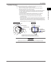
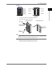
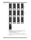
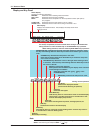
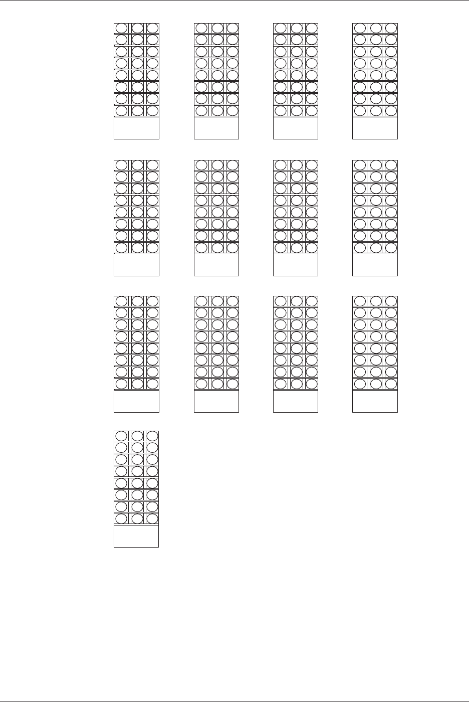
CE: Chart end
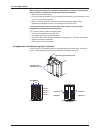
Alarm Output Relay Terminals and FAIL/Chart End Output Relay Terminals
NC (Normally Closed), C (Common), NO (Normally Opened)
Remote Control Input Terminals
1 to 5 (remote control input terminals), C (Common)
Alarm output terminals correspond to I01 to I06 in the alarm output relay settings.
Remote control input terminals 1 to 5 correspond to numbers 1 to 5 in the remote control
input settings.
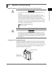
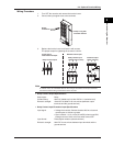
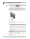
2.4 Optional Terminal Wiring