Index-3
Index
Index
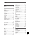
R Page
range type ...........................................................................1-2
rear panel ............................................................................3-3
recorder............................................................................... 1-1
recording ...........................................................................1-13
recording (computation channels)..................................... 1-25
recording color ......................................1-14, 7-8, 7-11, 9-23
recording span ....................................................................1-2
recording start printout ......................................................1-19
recording zone ..........................................................6-4, 9-15
reference junction compensation ........................................1-4
reference pen ....................................................................1-15
reference time ...................................................................7-14
reflash alarm .............................................................1-10, 7-3
registering display types to screens ....................................8-3
relational computation ...............................................1-24, 9-6
relative time mode............................................................. 9-21
relay contact input .............................................................2-11
relay contact output........................................................... 2-11
relay numbers .........................................................5-11, 9-12
releasing the alarm output ................................................3-18
releasing the key lock .......................................................3-19
remaining chart length ......................................................11-1
remote control .........................................................1-28, 7-28
remote control input terminals........................................... 2-10
remote signal ....................................................................1-29
replacement period for expendable parts .........................11-9
replacing felt pens ...............................................................3-7
replacing the internal light LED .........................................11-3
replacing the plotter pen .....................................................3-8
report data...............................................................7-14, 9-26
report mode.................................................................... App-2
resetting the computed values ............................................9-1
resetting the report data ....................................................3-17
resetting the TLOG computed value .................................9-22
revisions .................................................................................. i
ribbon cassette.................................................................. 3-10
ribbon feeding knob ..........................................................3-10
ribbon is loose ...................................................................3-10
RJC .....................................................................................7-7
RTD..................................................................................... 5-2
run modes ...........................................................................4-1
S Page
safety precautions ................................................................. iii
safety standards.................................................................... iii
safety symbols ...................................................................... iii
scale printout.................................................................. App-2
scaling .................................................................................1-3
scan interval ........................................................................1-2
secondary chart speed........................................................ 6-9
Setting complete screen .....................................................4-3
setting mode .......................................................................4-1
settings necessary to use various functions .....................4-13
Setup................................................................................. 3-14
setup guide .......................................................................4-13
setup items (basic setting mode) ......................................4-10
setup Items (setting mode) .................................................4-9
shunt resistor ......................................................................1-2
skip...................................................................................... 5-8
sprocket teeth .....................................................................3-5
square root ........................................................................1-24
square root computation .............................................1-3, 5-7
square root low-cut function ..............................................7-24
standard accessories ............................................................ vi
standard performance .....................................................12-19
standard temperature device ............................................11-5
start recording ...................................................................3-11
starting the computation...................................................... 9-1
status display ....................................................................1-22
status of the remote control input terminal ..........................9-5
stop recording ...................................................................3-11
stoppers ......................................................................3-4, 3-6
stopping the computation ....................................................9-1
suffix code .............................................................................. v
SUM scale..................................................... 7-14, 9-14, 9-26
supported standards .......................................................12-18
switching the display screen .............................................3-12
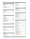
T Page
tag ...................................................................6-7, 7-11, 9-18
TC .......................................................................................5-2
temperature unit ................................................................7-31
thermocouple ......................................................................5-2
thermocouple input .............................................................2-6
time constant....................................................................... 6-2
time printout format .................................................1-18, 7-26
time tick ................................................................ 1-16, App-1
time tick cancel mark ........................................... 1-16, App-1
timer ..................................................................................9-21
TLOG computation.................................................... 1-24, 9-8
transistor input ..................................................................2-11
trend recording ......................................1-14, 6-6, 9-17, 12-4
trend recording interval .......................................................6-1
trigger ................................................................................1-29
troubleshooting .................................................................10-4
type of measured values ...................................................7-14
type of report data .............................................................9-26
types of computations .......................................................1-24
types of inputs .....................................................................1-2
U Page
unit ............................................................................5-12, 9-9
unit in computations ..........................................................1-25
V Page
VFD ...................................................................................1-22
Volt ......................................................................................5-2
W Page
wiring (measuring input )..................................................... 2-8
wiring (optional terminal) .....................................................2-9
wiring (power supply) ........................................................2-12
Z Page
zone recording ..................................................................1-14
Index


