


1-25
Functional Description
1
• Communication Input Data (Pen model: C01 to C08, dot model: C01 to C12)
This data type is set using the communication interface (/C7 or /C3 option).
Range of values (maximum significant digits is 5):
–9.9999E+29 to –1.0000E–30, 0, 1.0000E–30 to 9.9999E+29
For the procedure of setting the communication input data, see the RD100B/RD1800B
Communication Interface User’s Guide M-4233.
• Status of the Remote Control Input Terminal (D01 to D05, /R1 option)
The status of the remote control input signal (1 or 0) can be used in the computation.
Use D01 to D05 (the number following the letter D is the remote control input terminal
number) to specify the status in the equations.
<Related Topics>
Setting the computing equation, constant, and unit: Section 9.2 to 9.4
Setting the TLOG timer: Section 9.6 and 9.12
Handing of the Unit in Computations
In computations, measured/computed values are handled as values without units. For
example, if the measured value of channel 01 is 20 mV and the measured value of
channel 02 is 20 V, the computed result of 01 + 02 is 40.
Recording Computation Channels
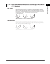
Trend Recording
Trend recording is possible by setting the recording span for each computation channel.
The recording span of computation channels can be set in the range of –9999999 to
99999999 excluding the decimal.
Zone recording and partial expanded recording are also possible.
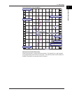
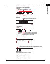
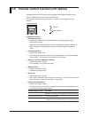
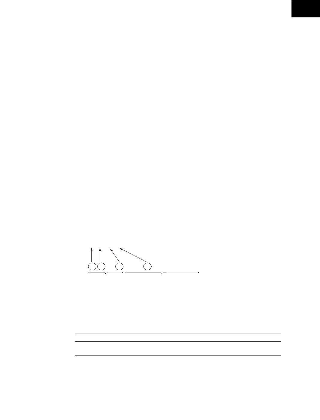
Assignment of Computation Channels to the Pens (Pen Model)
Trend recording is possible by assigning computation channels to arbitrary pens. Only
display or printout is possible for measurement channels or computation channels that
are not assigned to a pen. Assignment of pens is possible only on models with the
computation function.
Pen 1 2 3 4
Channel 01 02 03 04 0A 0B 0C 0D 0E 0F 0G 0J
Measurement channels Computation channels
<Related Topics>
Changing the channel assignment of recording pens: Section 9.14
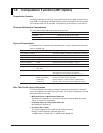
Changing the Channel Recording Color (Dot Model)
The recording colors of computation channels can be changed. The default recording
colors of channels are indicated below.
Recording color Purple Red Green Blue Brown Black
Computation channels 0A 0B 0C 0D 0E 0F
0G 0J 0K 0M 0N 0P
1.6 Computation Function (/M1 Option)