


2-6
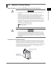
When using internal reference junction compensation on the thermocouple input,
take measures to stabilize the temperature at the input terminal.
• Always use the terminal cover.
• Do not use thick wires which may cause large heat dissipation (cross sectional area of
0.5 mm
2
or less recommended).
• Make sure that the ambient temperature remains reasonably stable. Large
temperature fluctuations can occur if a nearby fan turns ON or OFF.
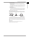
Connecting the input wires in parallel with other devices can cause signal
degradation, affecting all connected devices.
If you need to make a parallel connection, then
• Turn the burnout detection function OFF.
• Ground the instruments to the same point.
• Do not turn ON or OFF another instrument during operation. This can have adverse
effects on the other instruments.
• RTDs cannot be wired in parallel.
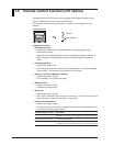
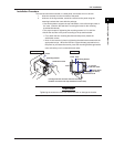
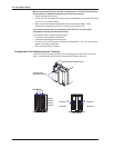
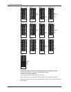
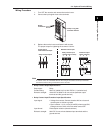
Arrangement of the Measuring Input Terminals
A terminal cover is screwed in place on the measuring input terminal block on the rear
panel. A label indicating the terminal arrangement is affixed to the cover.
Measuring input terminal block
Terminal cover
attachment screws
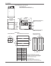
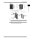
Pen Model
+/A
–/B
b
+/A
–/B
b
Channel 1
Channel 2
Channel 3
Channel 4
Channel 1
Channel 3
Channel 2
Channel 4
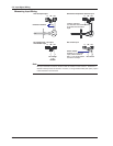
+/A
–/B
b
Screw input terminal Clamped input terminal
(/H2 option)
2.3 Input Signal Wiring