54
Connecting to the RS-232C Port at the Host Section 4-1
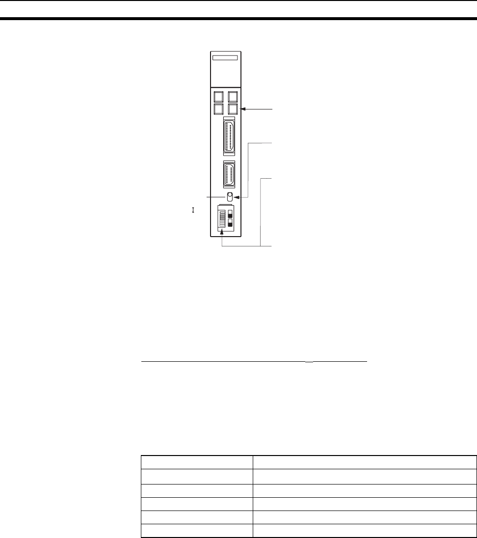
Setting The Front Switches
Connecting to a CPU Unit CV-series and CVM1/CV-series (-EV
@) CPU Units
CV500-CPU01-EV1/CV1000-CPU01-EV1/CV2000-CPU01-EV1
CVM1-CPU01-EV2/CVM1-CPU11-EV2/CVM1-CPU21-EV2
PLC Setup
When connecting to a CVM1/CV-series CPU Unit, set the following communi-
cations conditions for the PLC Setup.
*1
Set the host link communications speed at 9600 bps or 19200 bps with the
memory switch at the NT631/NT631C. For details, refer to 6-7-2 Setting the
Host Link Method (page 155).
Either set PLC Setup directly from a Programming Device (e.g. CX-Program-
mer), or transmit the PLC Setup made at a Programming Device to the CPU
Unit.
For details on the PLC Setup, refer to the SYSMAC CVM1/CV500/1000/2000
Operation Manual: Ladder Diagrams (W202-E1-@).
RS-232C
I/O port selector switch
RS-422A
• Unit # (SW3, SW4)
• Communications condition setting (DIP SW1)
Set this switch to OFF.
- Communications speed: 9600 bps
- Parity: Even
- Xon/Xoff control: Not executed
- Communications method: Full duplex
- Stop bits: 2 stop bits
- Data length: 7 bits
• I/O port selection (selector switch)
Set this to RS-232C.
• CTS selection (DIP SW2 and SW3)
Set SW2 or SW3 to ON. (Set this always to 0 V.)
Communications port 1
(RS-232C)
Communications port 2
(RS-232C/RS-422A)
When using communications port 2, set
these switches to 0.
To use communications port 1, set SW2. To
use communications port 2, set SW3.
Communications are executed in
accordance with the CPU Bus Unit system
settings made at the PLC. The initial values
for the system settings are as follows.
Item Setting at Host
Communications speed
Set the same speed as set at the NT631/NT631C
(*1)
Stop bit 2 stop bits
Parity Even
Data length ASCII 7 bits
Unit # 00


