


EN-9
Main Circuit Terminals
Main circuit terminal functions are summarized according to terminal symbols in Table 1. Wire the
terminals correctly for the desired purposes.
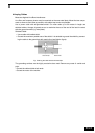
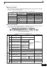
Table 1 Main Circuit Terminal Functions (200 V Class and 400 V Class)
Control Circuit Terminals
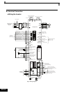
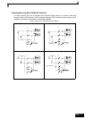
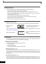
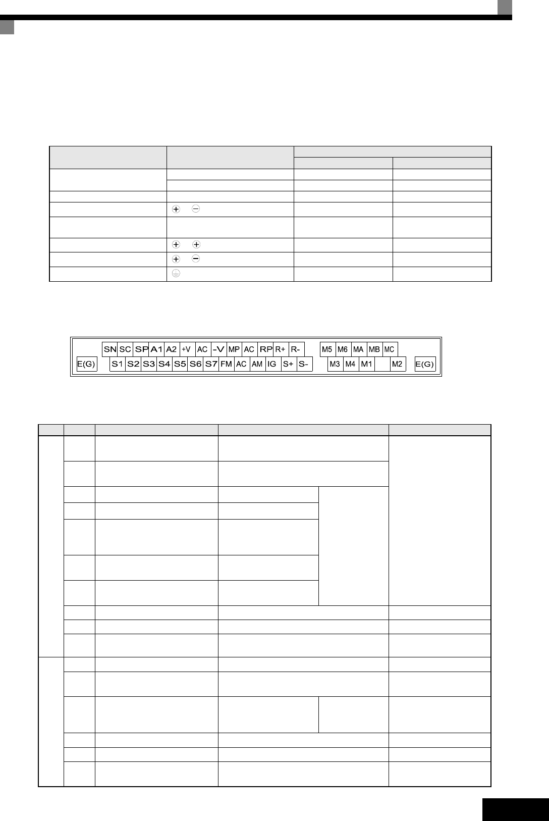
Fig 5 shows the control terminal arrangement. The functions of the control circuit terminals are
shown in Table 2 . Use the appropriate terminals for the correct purposes.
Fig 5 Control terminal arrangement
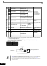
Table 2 Control Circuit Terminals with default settings
Purpose Terminal Symbol
Model: CIMR-F7Z
200 V Class 400 V Class
Main circuit power input
R/L1, S/L2, T/L3 20P4 to 2110 40P4 to 4300
R1/L11, S1/L21, T1/L31 2022 to 2110 4022 to 4300
Inverter outputs U/T1, V/T2, W/T3 20P4 to 2110 40P4 to 4300
DC bus terminals
1,
20P4 to 2110 40P4 to 4300
Braking Resistor Unit Connec-
tion
B1, B2 20P4 to 2018 40P4 to 4018
DC reactor connection
1, 2
20P4 to 2018 40P4 to 4018
Braking Unit connection
3,
2022 to 2110 4022 to 4300
Ground 20P4 to 2110 40P4 to 4300
Ty pe No. Signal Name Function Signal Level
Digital input signals
S1 Forward run/stop command
Forward run when ON; stopped when
OFF.
24 VDC, 8 mA
Photocoupler isolation
S2 Reverse run/stop command
Reverse run when ON; stopped when
OFF.
S3
External fault input
*1
Fault when ON.
Functions are
selected by set-
ting H1-01 to
H1-05.
S4
Fault reset
*1
Reset when ON
S5
Multi-step speed reference 1
*1
(Master/auxiliary switch)
Auxiliary frequency ref-
erence when ON.
S6
Multi-step speed reference 2
*1
Multi-step speed 2
when ON.
S7
Jog frequency reference
*1
Jog frequency when
ON.
SC Digital input common – –
SN Digital Input Neutral – –
SP Digital Input Power Supply +24VDC power supply for digital inputs
24 VDC, 250 mA max.
*2
Analog input signals
+V 15 V power output 15 V power supply for analog references 15 V (Max. curr.: 20mA)
A1 Frequency reference 0 to +10 V/100%
-10 to +10 V (20 kΩ)
0 to +10 V (20 kΩ)
A2
Auxiliary Frequency Refer-
ence
Auxiliary analog fre-
quency reference;
4 to 20 mA (250Ω)
Function is
selected by set-
ting H3-09.
4 to 20 mA (250 Ω)
0 V to +10 V (20 kΩ)
0 to 20 mA (250 Ω)
-V -15 V power output -15 V power supply for analog references
AC Analog reference common – –
E(G)
Shield wire, optional ground
line connection point
––