EN-16
Before Power Up
The following points should be checked carefully before the power is switched on.
• Check if the power supply meets the inverter specification.
• Check if the power supply cables are tightly connected to the right terminals (L1, L2, L3).
• Check if the motor cables are tightly connected to the right terminals on the inverter side (U, V,
W) as well as on the motor side.
• Check if the braking unit / braking resistor is connected correctly.
• Check if the Inverter control circuit terminal and the control device are wired correctly.
• Set all Inverter control circuit terminals to OFF.
• When a PG card is used, check if it is wired correctly.
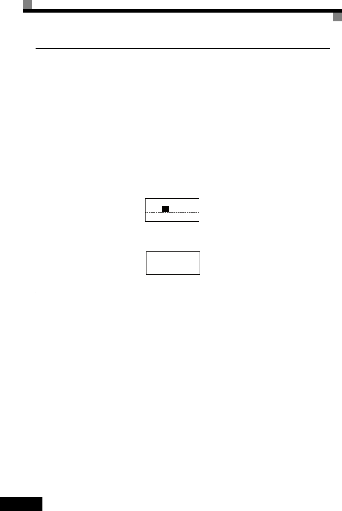
Display after Power Up
After normal power up without any problems the operator display shows the following messages
When a fault has occurred or an alarm is active a fault or alarm message will appear. In this case,
refer to page 21, Troubleshooting.
Autotuning
Autotuning sets motor parameters automatically when using Open Loop or Closed Loop Vector con-
trol, when the cable length is long or the installation has changed.
Setting the Autotuning Mode
One of the following three autotuning modes can be set.
• Rotating autotuning
• Non-rotating autotuning
• Non-rotating autotuning for line-to-line resistance only
Rotating Autotuning (T1-01 = 0)
Rotating autotuning is used for Open Loop and Closed Loop Vector control only. Set T1-01 to 0,
input the data from the motor nameplate, and then press the RUN key on the Digital Operator. The
Inverter will operate the motor for approximately 1 minute and set the required motor parameters
automatically.
Non-rotating Autotuning (T1-01 = 1)
Non-rotating autotuning is used for Open Loop and Closed Loop Vector control only. Set T1-01 to 1,
input the data from the motor nameplate, and then press the RUN key on the Digital Operator. The
inverter will supply power to the non-rotating motor for approximately 1 minute and some of the
Display for normal
operation
The frequency reference monitor is dis-
played in the data display section.
Display for fault operation
A fault or alarm message is shown on the
display.
The example shows a low voltage alarm.
Frequency Ref
-DRIVE-
U1-02=50.00Hz
U1-03=10.05A
Rdy
U1- 01=50.00Hz
-DRIVE-
UV
DC Bus Undervolt


