


EN-7
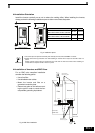
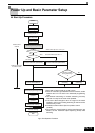
Installation Orientation
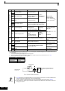
Install the Inverter vertically so as not to reduce the cooling effect. When installing the Inverter,
always provide the following installation space to allow normal heat dissipation.
Fig 2 Installation space
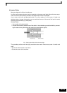
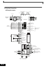
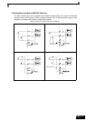
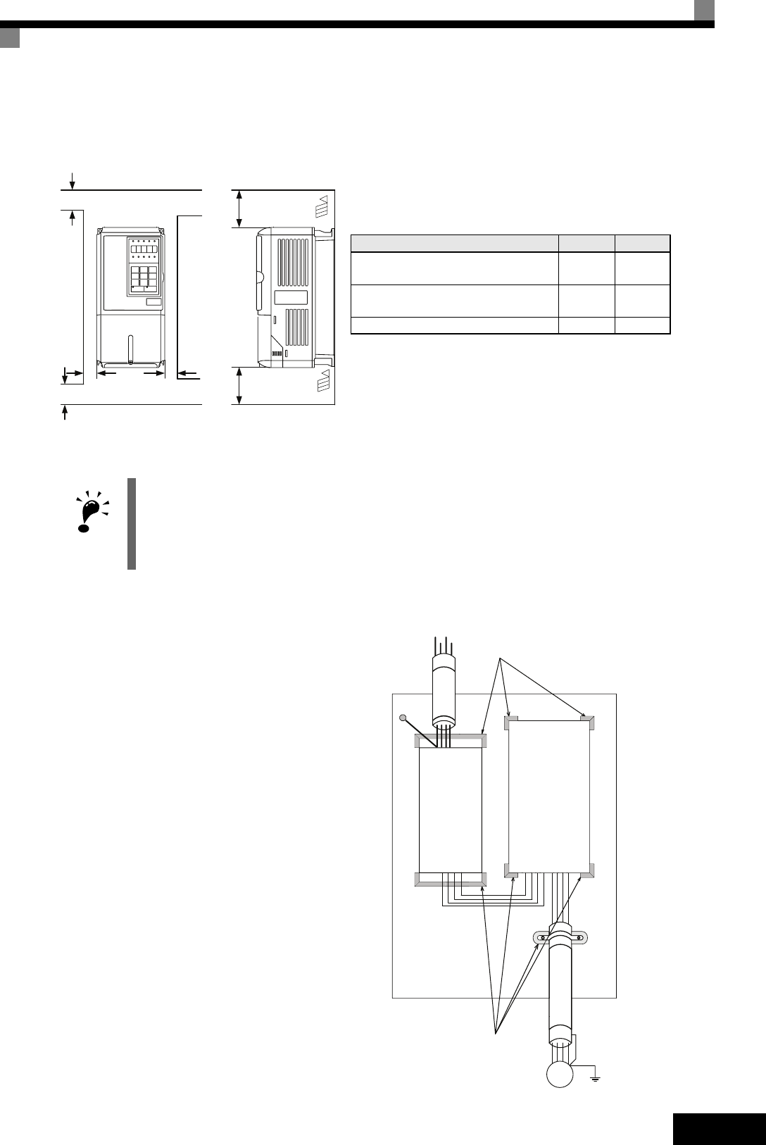
Installation of Inverters and EMC filters
For an EMC rules compliant installation
consider the following points:
• Use a line filter.
• Use shielded motor cables.
• Mount the inverter and filter on a
grounded cunductive plate.
• Remove any paint or dirt before mount-
ing the parts in order to reach the low-
est possible grounding impedance.
Fig 3 EMC filter installation
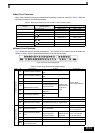
IMPORTANT
1. The same space is required horizontally and vertically for IP00, IP20 and NEMA 1 Inverters.
2. Always remove the top protection cover after installing an Inverter with an output of 18.5 kW or less in a
panel.
Always provide enough space for suspension eye bolts and the main circuit lines when installing an
Inverter with an output of 22 kW or more in a panel.
A
B
Horizontal Space
50mm
min.
30mm min.
30mm min.
120mm min.
Air
Air
Vertical Space
A B
200V class inverter, 0.55 to 90 kW
400V class inverter, 0.55 to 132 kW
50 mm 120 mm
200V class inverter, 110 kW
400V class inverter, 160 to 220 kW
120 mm 120 mm
400V class inverter, 300 kW 300 mm 300 mm
Ground Bonds
Remove any paint!
PE
L1
L2
L3
PE
Line
Filter
Ground Bonds
Remove any paint!
Load
GND
L1
L2
L3
GND
U
V
W
M
~3
Screened
Motor cable
Cable Lenght
as short as possible
Grounded
Metal Plate
Inverter