


EN-18
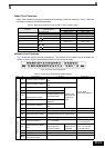
Param-
eter
Num-
ber
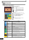
Name Description
Initialize Data
A1-00
Language
selection for
Digital Opera-
tor dis-
play(JVOP-
160-OY only)
0:English
2:German
3:French
4:Italian
5:Spanish
6:Portuguese
A1-01
Parameter
access level
0:Monitoring only (Monitoring drive
mode and setting A1-01 and A1-04.)
1:Used to select user parameters (Only
parameters set in A2-01 to A2-32 can
be read and set.)
2:Advanced
(Parameters can be read and set in
both, quick programming mode (Q)
and advanced programming mode
(A).
A1-02
Control method
selection
0:V/f control
1:V/f control with PG
2:Open loop vector control
3:Closed loop vector control
A1-03 Initialize
0: No initializing
1110:Initializes using the user
parameters
2220:Initializes using a two-wire
sequence. (Initializes to the factory
setting.)
3330: Initializes using a three-wire
sequence.
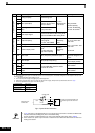
Sequence / Reference Source
b1-01
Reference
source selec-
tion
Sets the frequency reference input
method.
0:Digital Operator
1:Control circuit terminal (analog input)
2:Serial communication (RS422 / 485)
3:Option Card
b1-02
RUN com-
mand source
selection
Sets the run command input method.
0:Digital Operator
1:Control circuit terminal (digital inputs)
2:Serial communication (RS422 / 485)
3:Option Card
b1-03
Stopping
method selec-
tion
Selects the stopping method when the
Run signal is removed
0:Deceleration to stop
1:Coast to stop
2:DC injection to stop
3:Coast to stop with timer (New Run
commands are disregarded while
coasting.)
b1-04
Prohibition of
reverse opera-
tion
0:Reverse enabled
1:Reverse disabled
2:Output Phase Rotation (both rota-
tional directions are enabled)
3:Output Phase Rotation with Reverse
disabled.
Acceleration / Deceleration Settings
C1-
Acceleration/
Deceleration
times
Sets the time to accelerate/decelerate
from 0 Hz to the maximum output fre-
quency.
S-Curve Settings
C2-
S-curve char-
acteristic time
at acceleration
Sets the S-curve characteristic at accel-
eration start and end.
Motor Slip Compensation (not available in V/f with
PG)
C3-01
Slip compensa-
tion gain
Used to improve speed accuracy
• Increase if output frequency is too low
• Decrease if output frequency is too
high.
C3-02
Slip compensa-
tion delay time
(only available
in V/f and OLV)
Sets the slip compensation delay time
• Increase if output frequency is not
stable
• Decrease setting when slip compen-
sation responsiveness is low.
Speed Control (ASR) (only available in V/f with PG
and CLV)
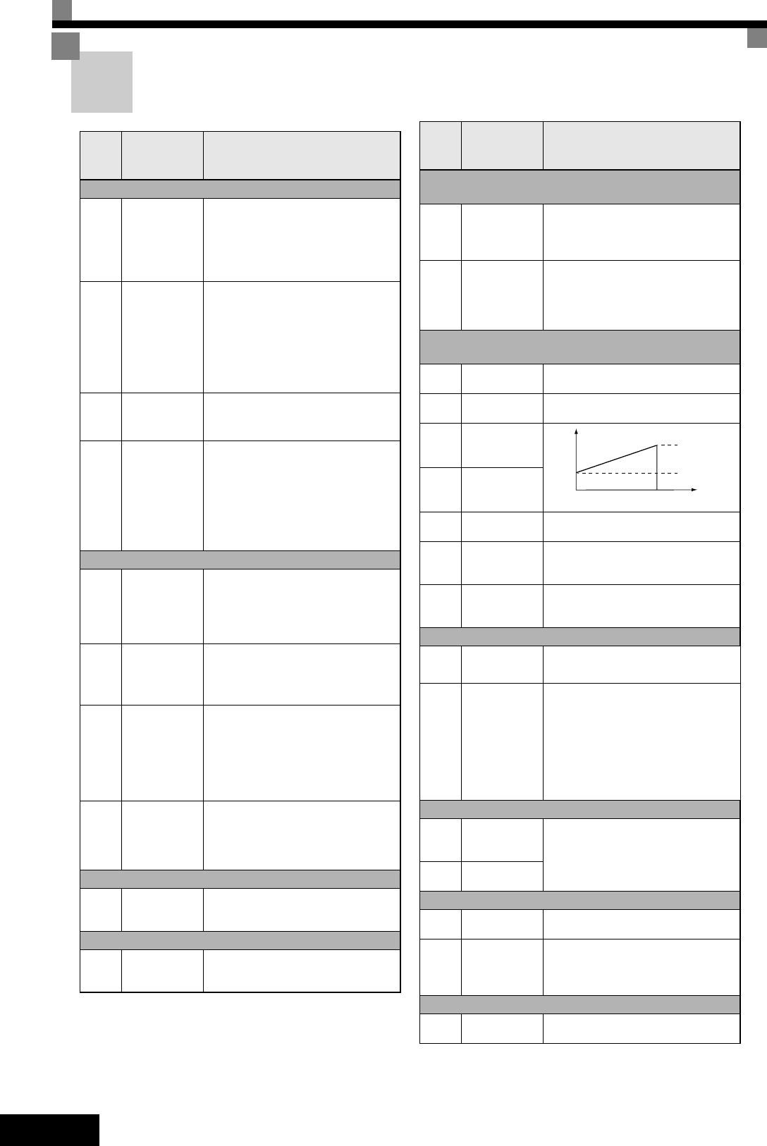
C5-01
ASR propor-
tional gain 1
Sets the proportional gain of the speed
loop (ASR)
C5-02
ASR integral
time 1
Sets the integral time of the speed loop
(ASR)
C5-03
ASR propor-
tional gain 2
C5-04
ASR integral
time 2
C5-06
ASR delay time
(only CLV)
Sets the ASR filter time constant.
C5-07
ASR switching
frequency
(only CLV)
Sets the frequency for switching
between ASR gain 1, 2 and ASR integral
time 1, 2
C5-08
ASR integral
limit
(only CLV)
Sets the limit for the integral part of the
ASR controller.
Carrier Frequency
C6-01
Heavy/Normal
duty selection
0:Heavy Duty
1:Normal Duty 1
2:Normal Duty 2
C6-02
Carrier fre-
quency selec-
tion
Selects the carrier frequency (factory
setting depends on Inverter capacity)
0: Low noise, low carrier
1: 2.0 kHz
2: 5.0 kHz
3: 8.0 kHz
4: 10.0 kHz
5: 12.5 kHz
6: 15.0 kHz
F: Programmable pattern
Speed Settings
d1-01
to
d1-16
Multi speed
references 1 to
16
Sets the multi-step speed references.
d1-17
Jog frequency
reference
Torque Control (only available in CLV)
d5-01
Torque control
selection
0:Speed control
1:Torque control
d5-06
Speed/torque
control switch
over timer
Sets the delay from inputting a “speed/
torque control change” signal (by digital
input) until the control is acutally
changed
V/f Pattern Settings
E1-01
Input voltage
setting
This setting is used as a reference value
for protection functions.
Param-
eter
Num-
ber
Name Description
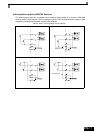
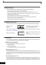
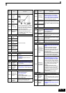
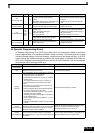
P, I
0 E1-04
P=C5-01
I=C5-02
P=C5-03
I=C5-04
Motor
speed (Hz)
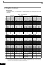
User Parameter