


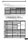
EN-22
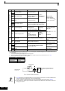
OC
Over Current
Over Current
The Inverter’s output current exceeded the over-
current detection level.
• Remove the motor and run the Inverter
without the motor.
• Check the motor for a phase-to-phase
short.
• Verify the accel/decel times (C1-).
• Check the Inverter for a phase-to-phase
short at the output.
OH
Heatsnk Overtemp
Heatsink Overheat
L8-03 = 0,1 or 2 and the temperature of the
Inverter's cooling fin exceeded the L8-02 value.
• Check for dirt build-up on the fans or heat-
sink.
• Reduce the ambient temperature around
the drive.
• Replace the cooling fan(s).
Inverter's Cooling Fan Stopped
L8-03 = 3 or 4 and the temperature of the
Inverter's cooling fin exceeded the L8-02 value.
OH1
Heatsink Max Temp
Heatsink Overheat
The temperature of the Inverter’s heatsink
exceeded 105 °C.
• Check for dirt build-up on the fans or heat-
sink.
• Reduce the ambient temperature around
the drive.
• Replace the cooling fan(s).
Inverter’s Cooling Fan Stopped
OL1
Motor Overload
Motor Overload
Detected when L1-01 is set to 1,2 or 3 and the
Inverter’s I²t value exceeded the motor overload
curve.
The overload curve is adjustable using parame-
ter
E2-01 (Motor Rated Current), L1-01 (Motor Pro-
tection Selection) and L2-02 (Motor Protection
Time Constant)
• Recheck the cycle time and the size of the
load as well as the accel/decel times (C1-
).
• Check the V/f characteristics (E1-).
• Check the setting of Motor Rated Current
Setting (E2-01).
OL2
Inv Overload
Inverter Overload
The Inverter output current exceeded the Invert-
ers’s overload capability
• Recheck the cycle time and the size of the
load as well as the accel/decel times (C1-
).
• Check the V/f Characteristics (E1-).
• Check if the inverter rated current matches
the motor rated current.
OS
Overspeed Det.
F1-03 = 0, 1 or 2 and A1-02 = 1 or 3
The motor speed feedback (U1-05) exceeded
the setting in F1-08 for a time longer than the
setting of
F1-09
• Adjust the ASR settings in the C5 parame-
ter groupt
• Check the reference circuit and reference
gain.
• Check the settings in F1-08 and F1-09
F1-03 = 3 and A1-02 = 1 or 3
The motor speed feedback (U1-05) exceeded
the setting in F1-08 for a time longer than the
setting of
F1-09
OV
DC Bus Overvolt
(only in
stop
condi-
tio)
The DC bus voltage has exceeded the overvolt-
age detection level.
Default detection levels are:
200 V class: 410 VDC
400 V class: 820 VDC
• Increase the deceleration time (C1-02/04)
or connect a braking option.
• Check the power supply and decrease the
voltage to meet the inverter’s specifica-
tions.
• Check the braking chopper / resistor.
PF
Input Phase Loss
Input Phase Loss
Too big DC bus voltage ripple.
Only detected when L8-05=1 (enabled)
• Tighten the input terminal screws
• Check the power supply voltage
PGO
PG Open
PG Disconnection
Detected when F1-02 = 0, 1 or 2 and A1-02 = 1
or 3.
Detected when no PG (encoder) pulses have
been received for a time longer than the setting
in F1-14.
• Fix the broken/disconnected wiring.
• Supply power to the PG properly.
• Check the sequence and if the brake is
opened when the inverter starts to increase
the speed.
PG Disconnection
Detected when F1-02 = 3 and A1-02 = 1 or 3.
PG (encoder) pulses have not been received for
a time longer than the setting in F1-14.
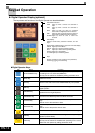
Display
Alarm Fault
Meaning Corrective Actions