


EN-10
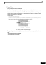
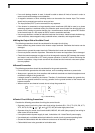
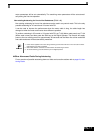
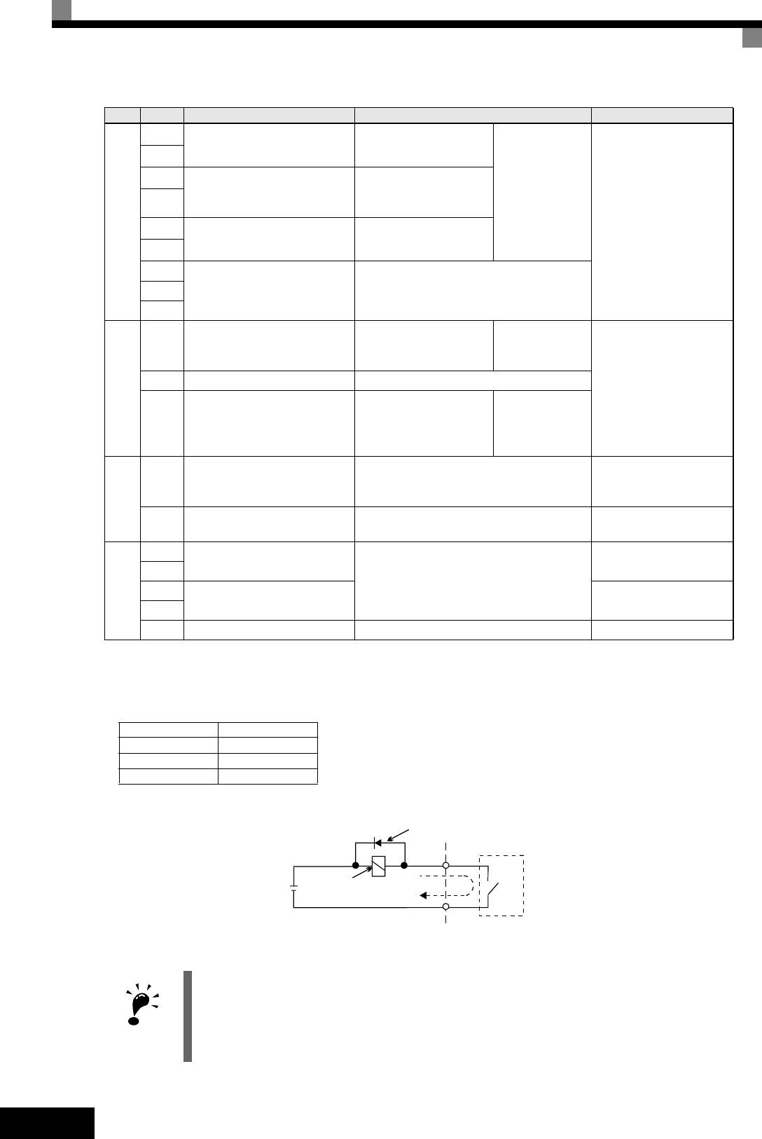
Fig 6 Flywheel Diode Connection
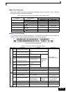
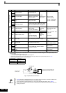
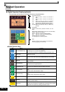
Digital output signals
M1
During run (NO) Closed during Run
Function
selected by H2-
01 to H2-03
Relay contacts
Contact capacity:
1 A max. at 250 VAC
1 A max. at 30 VDC
*3
M2
M3
Zero speed (NO)
Closed when output
frequency at zero level
(b2-01) or below
M4
M5
Speed agreement detection
(NO)
Within ± 2 Hz of set fre-
quency when ON
M6
MA
Fault output signal
Closed across MA and MC during faults
Open across MB and MC during faults
MB
MC
Analog output signals
FM Output frequency
Analog output fre-
quency signal;
0 to 10 V; 10V=FMAX
Function
selected by
H4-01
0 to +10 V max. ±5%
2 mA max.
-10 to +10 V max. ±5%
2 mA max
4 to 20 mA
AC Analog common –
AM Inverter output power
Analog output power
signal;
0 to 10V; 10V=max.
appl. motor capacity
Function
selected by
H4-04
Pulse I/O
RP Pulse Input
H6-01 (Frequency reference input)
*4
0 to 32 kHz (3kΩ)
High level voltage 3.5 to
13.2 V
MP Pulse Output H6-06 (Output frequency)
0 to 32 kHz
+15 V output (2.2kΩ)
RS-485/422
R+
MEMOBUS communications
input
For 2-wire RS-485, short R+ and S+
as well as R- and S-.
Differential input,
PHC isolation
R-
S+
MEMOBUS communications
output
Differential input,
PHC isolation
S-
IG Signal common – –
*1. The default settings are given for terminals S3 to S7. For a 3-wire sequence, the default settings are a 3-wire sequence for S5, multi-
step speed setting
1 for S6 and multi-step speed setting 2 for S7.
*2. Do not use this power supply for supplying any external equipment.
*3. When driving a reactive load, such as a relay coil with DC power supply, always insert a flywheel diode as shown in Fig 6
*4. Pulse input specifications are given in the following table:
Low level voltage 0.0 to 0.8 V
High level voltage 3.5 to 13.2 V
H duty 30% to 70%
Pulse frequency 0 to 32 kHz
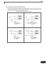
IMPORTANT
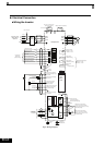
1. In Fig 4 the wiring of the digital inputs S1 to S7 is shown for the connection of contacts or NPN transis-
tors (0V common and sinking mode). This is the default setting.
For the connection of PNP transistors or for using a 24V external power supply, refer to Table 3.
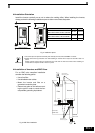
2. A DC reactor is an option only for Inverters of 18.5 kW or less. Remove the short circuit bar when con-
necting a DC reactor.
Ty pe No. Signal Name Function Signal Level
External power:
30 VDC max.
Coil
Flywheel diode
1 A max.
The rating of the flywheel diode must
be at least as high as the circuit volt-
age.