


EN-20
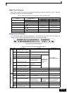
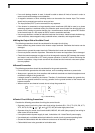
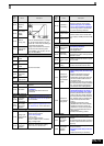
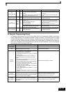
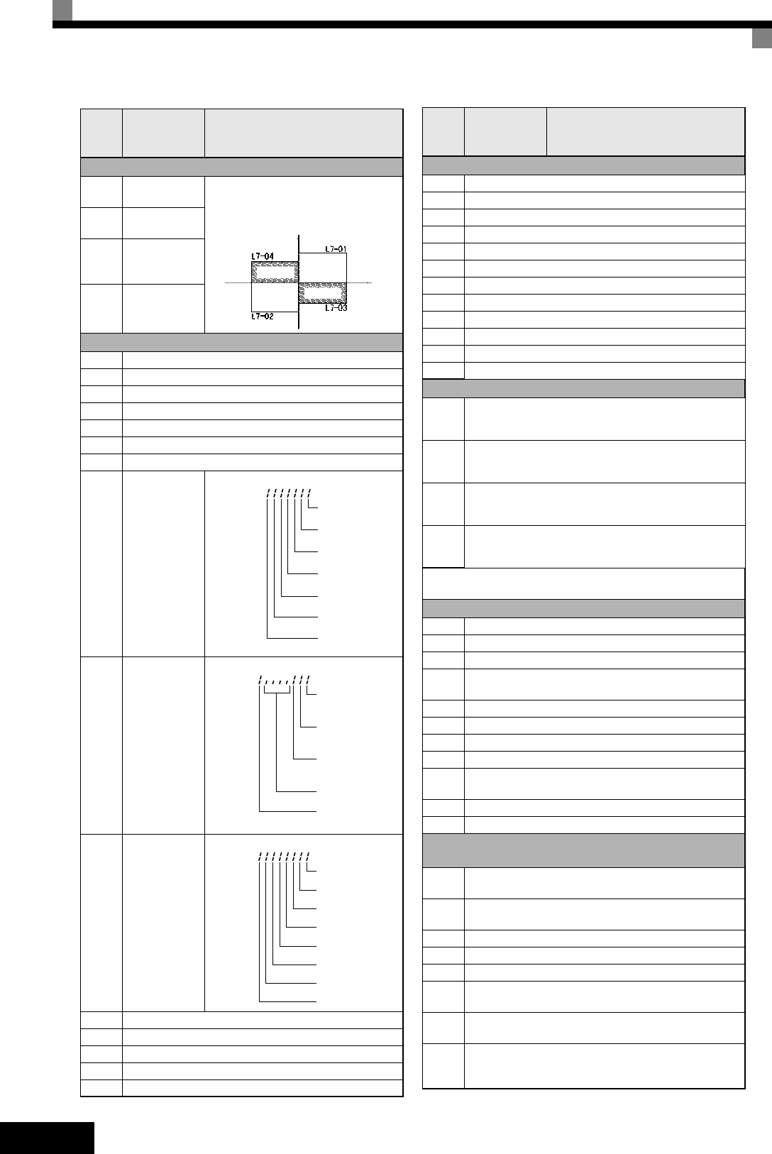
Torque Limit (only OLV and CLV)
L7-01
Forward drive
torque limit
Sets the torque limit vlaue as a per-
centage of the motor rated torque.
Four individual regions can be set.
L7-02
Reverse drive
torque limit
L7-03
Forward
regenerative
torque limit
L7-04
Reverse
regenerativ
torque limit
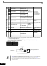
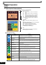
Monitor Data
U1-01 Frequency reference in Hz / rpm
U1-02 Output frequency in Hz / rpm
U1-03 Output current in A
U1-06 Output voltage in VAC
U1-07 DC bus voltage in VDC
U1-08 Output power in kW
U1-09 Torque reference
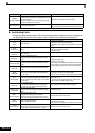
U1-10
Input terminal
status
Shows input ON/OFF status.
U1-11
Output termi-
nal status
Shows output ON/OFF status.
U1-12
Operation sta-
tus
Inverter operating status.
U1-13 Cumulative operation time in hrs.
U1-21 ASR input
U1-22 ASR output
U1-34 OPE fault parameter
U1-40 Cooling fan operating time in hrs.
Param-
eter
Num-
ber
Name Description
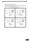
Output torque
Positive torque
Reverse
Negative torque
No.
o
motor
rotations
Regen.
Forward
Regen.
U1-10 =
1: FWD command
(S1) is ON
1: REV command
(S2) is ON
1: Multi input 1
(S3) is ON
1: Multi input 2
(S4) is ON
1: Multi input 3
(S5) is ON
1: Multi input 4
(S6) is ON
1: Multi input 5
(S7) is O N
U1-11 =
1: Multi-function
contact output 1
(M1-M2) is ON
1: Multi-function
contact output 2
(M3-M4) is ON
1: Multi-function
contact output 3
(M5-M6) is ON
Not used
(Always 0).
1: Error output
(MA/MB-MC) is ON
U1-12 =
Run
1: Zero speed
1: Reverse
1: Reset signal input
1: Speed agree
1: Inverter ready
1: Minor fault
1: Major fault
Fault Trace Data
U2-01 Current fault
U2-02 Last fault
U2-03 Reference frequency at fault
U2-04 Output frequency at fault
U2-05 Output current at fault
U2-07 Output voltage reference at fault
U2-08 DC bus voltage at fault
U2-09 Output power at fault
U2-11 Input terminal status at fault
U2-12 Output terminal status at fault
U2-13 Operation status at fault
U2-14 Cumulative operation time at fault
Fault History Data
U3-01
to
U3-04
Last fault to fourth last fault
U3-05
to
U3-08
Cumulative operation time at fault 1 to 4
U3-09
to
U3-14
Fifth last to tenth last fault
U3-15
to
U3-20
Accumulated time of fifth to tenth fault
* The following faults are not recorded in the error log:
CPF00, 01, 02, 03, UV1, and UV2.
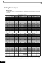
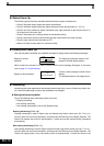
Digital Input Function Selections (H1-01 to H1-05)
3 Multi-step speed reference 1
4 Multi-step speed reference 2
5 Mulit-step speed reference 3
6
Jog frequency command (higher priority than multi-
step speed reference)
7 Accel/decel time selection 1
F Not used (Set when a terminal is not used)
14 Fault reset (Reset when turned ON)
19 PI control disable
20 to
2F
External fault; Input mode: NO contact/NC contact,
Detection mode: Normal/during operation
71 Speed/torque control change (ON: Torque control)
77 Speed control (ASR) gain switching (ON: C5-03)
Digital Output Function Selections
(H2-01 and H2-02
0
During run 1 (ON: run command is ON or voltage is
being output)
6
Inverter operation ready; READY: After initialization or
no faults
F Not used. (Set when the terminal is not used.)
10 Minor fault (Alarm) (ON: Alarm displayed)
1A During reverse run (ON: During reverse run)
1F
Motor overload (OL1, including OH3) pre-alarm (ON:
90% or more of the detection level)
30
During torque limit (current limit) (ON: During torque
limit)
32
Activated if the ASR is operating for torque limit. The
ASR output becomes the torque reference, the motor
is rotating at the speed limit.
Param-
eter
Num-
ber
Name Description