


EN-19
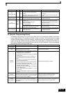
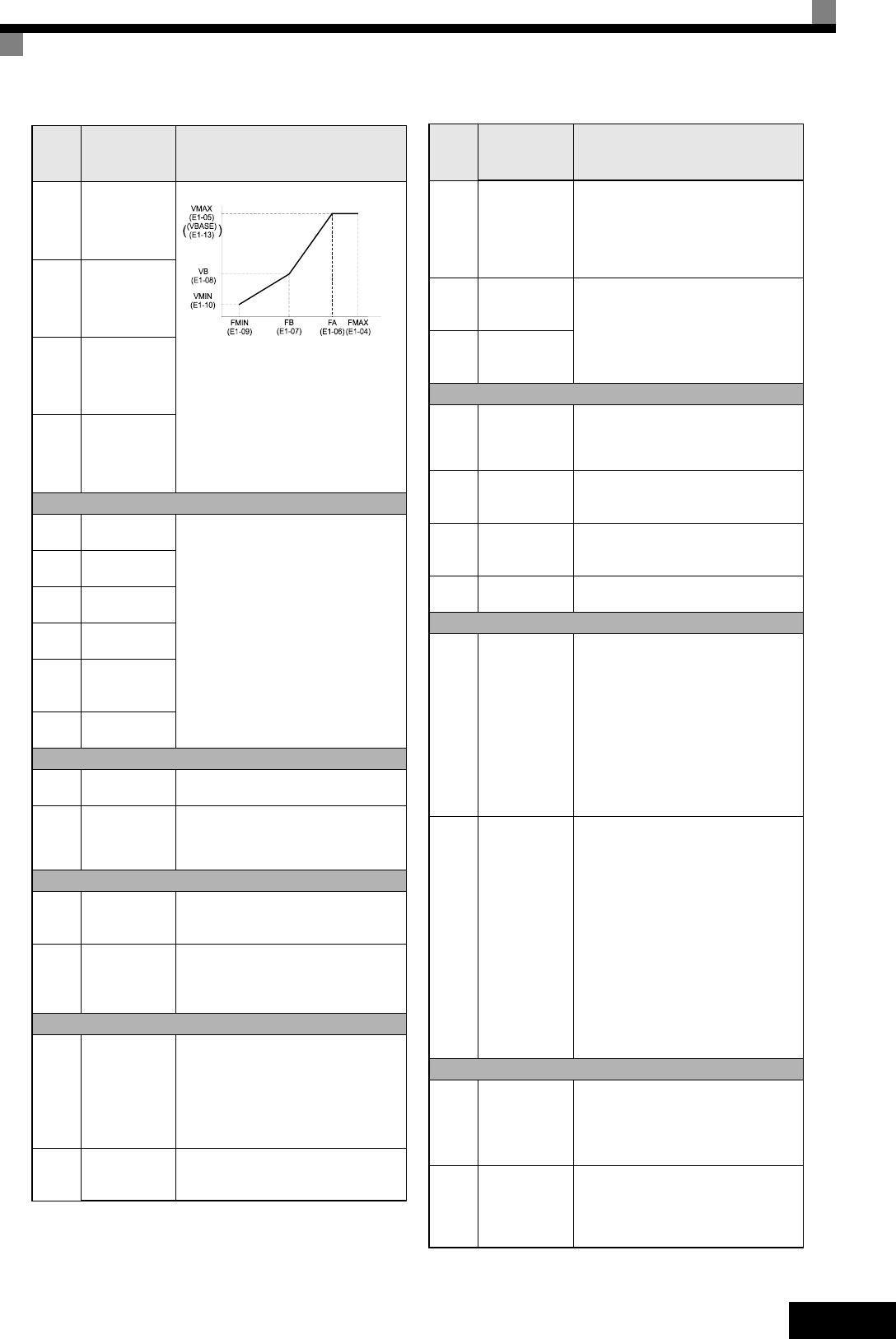
E1-04
Max. output
frequency
(FMAX)
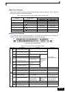
To set V/f characteristics in a straight
line, set the same values for E1-07
and E1-09. In this case, the setting for
E1-08 will be disregarded.
Always ensure that the four frequen-
cies are set in the following order:
E1-04 (FMAX) ≥ E1-06 (FA) > E1-07
(FB) ≥ E1-09 (FMIN)
E1-05
Max. output
voltage
(VMAX)
E1-06
Base fre-
quency (FA)
E1-13
Base Voltage
(VBASE)
Motor Data Settings
E2-01
Motor rated
current
Sets the motor data.
E2-02
Motor rated
slip
E2-03
Motor no-load
current
E2-04
Number of
motor poles
E2-09
Motor
mechanical
losses
E2-11
Motor rated
output power
PG Option Setup
F1-01 PG constant
Sets the number of PG pulses per
revolution
F1-05 PG rotation
0:Phase A leads with forward run
command
1:Phase B leads with forward run
command
Digital I/O Settings
H1-01
to
H1-05
Terminal S3 to
S7 function
selection
Refer to page 20, Digital Input Func-
tion Selections (H1-01 to H1-05) for a
list of selections
H2-01
and
H2-02
Terminal M1-
M2 and M3-
M4 function
selection
Refer to page 20, Digital Output Func-
tion Selections for a list of selections
Analog I/O Settings
H3-08
Analog input
A2 signal level
selection
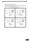
Selects the signal level input at multi-
function analog input A2.
0:0 to +10 V (11 bit).
1:-10 to +10 V
2:4 to 20 mA (9-bit input).
Ensure to switch S1-2 to “V” before
using a voltage input.
H3-09
Analog input
A2 function
selection.
Selects the multi-function analog
input function for terminal A2.
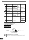
Param-
eter
Num-
ber
Name Description
Output Voltage (V)
Frequency (Hz)
H3-13
Terminal A1/
A2 switching
Selects on which terminal the main
frequency reference can be input.
0:Use analog input 1 on terminal
A1 for main frequency reference.
1:Use analog input 2 on terminal A2
for main frequency reference.
H4-01
Terminal FM
monitor selec-
tion
Sets the number of the monitor item
to be output (U1-) at terminal FM/
AM.
H4-04
Terminal AM
monitor selec-
tion
Pulse Train I/O
H6-01
Pulse train
input function
selection
Selects the pulse train input function
0:Frequency reference
1:PID feedback value
2:PID target value
H6-02
Pulse train
input scaling
Sets the number of pulses in Hz that
is equivalent to 100% of the input item
selected in H6-01.
H6-06
Pulse train
monitor selec-
tion
Selects the pulse train monitor output
item (U1-)
H6-07
Pulse monitor
scaling
Sets the number of pulses output in
Hz when the monitor item is 100%.
Stall Prevention
L3-01
Stall preven-
tion selection
during accel
(not available
in CLV)
0:Disabled (Acceleration as set.
With a heavy load, the motor may
stall.)
1:Enabled (Acceleration stopped
when L3-02 level is exceeded.
Acceleration starts again when the
current has fallen below the stall
prevention level).
2:Intelligent acceleration mode (Using
the L3-02 level as a basis, accelera-
tion is automatically adjusted. Set
acceleration time is disregarded.)
L3-04
Stall preven-
tion selection
during decel
0:Disabled (Deceleration as set. If
deceleration time is too short, a
DC bus overvoltage may result.)
1:Enabled (Deceleration is stopped
when the DC bus voltage exceeds
the stall prevention level. Decelera-
tion restarts when the voltage falls
below the stall prevention level
again.)
2:Intelligent deceleration mode
(Deceleration rate is automatically
adjusted so that the Inverter can
decelerate in the shortest possible
time. The set deceleration time is
disregarded.)
3:Enabled with braking resistor
Fault Restart
L5-01
Number of
auto restart
attempts
Sets the number of auto restart
attempts.
Automatically restarts after a fault and
conducts a speed search from the run
frequency.
L5-02
Auto restart
operation
selection
Sets whether a fault relay is activated
during fault restart.
0:No output (Fault relay is not acti-
vated.)
1:Output (Fault relay is activated.)
Param-
eter
Num-
ber
Name Description