EN-13
• If an earth leakage breaker is used, it should be able to detect all kinds of current in order to
ensure a safe earth leakage current detection
• A magnetic contactor or other switching device can be used at the inverter input. The inverter
should not be powered up more than once per hour.
• The input phases (R/S/T) can be connected in any sequence.
• If the Inverter is connected to a large-capacity power transformer (600 kW or more) or a phase
advancing capacitor is switched nearby, an excessive peak current could flow through the input
power circuit, causing an inverter damage. As a countermeasure install an optional AC Reactor
at the inverter input or a DC reactor at the DC reactor connection terminals.
• Use a surge absorber or diode for inductive loads near the Inverter. Inductive loads include mag-
netic contactors, electromagnetic relays, solenoid valves, solenoids, and magnetic brakes.
Wiring the Output Side of the Main Circuit
The following precautions should be considered for the output circuit wiring.
• Never connect any power source to the inverter output terminals. Otherwise the inverter can be
damaged.
• Never short or ground the output terminals. Otherwise the inverter can be damaged.
• Do not use phase correction capacitors. Otherwise the inverter and capacitors can be damaged.
• Check the control sequence to make sure, that the magnetic contactor (MC) between the Inverter
and motor is not turned ON or OFF during inverter operation. If the MC is turned ON during the
Inverter is operation, a large inrush current will be created and the inverter’s overcurrent protec-
tion may operate.
Ground Connection
The following precautions should be considered for the ground connection.
• Do not share the ground wire with other devices, such as welding machines or power tools.
• Always use a ground wire, that complies with technical standards on electrical equipment and
minimize the length of the ground wire.
Leakage current is caused by the Inverter. Therefore, if the distance between the ground elec-
trode and the ground terminal is too long, potential on the ground terminal of the Inverter will
become unstable.
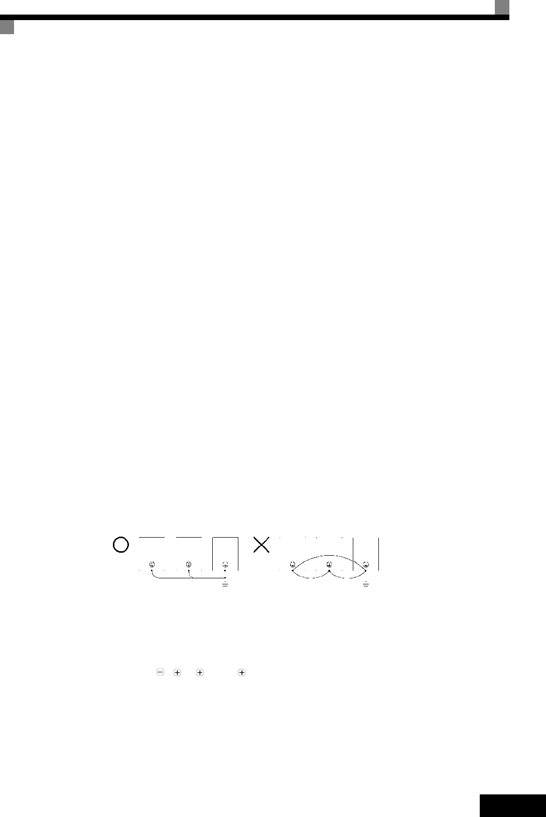
• When more than one Inverter is used, do not to loop the ground wire.
Fig 7 Ground Wiring
Control Circuit Wiring Precautions
Consider the following precautions for wiring the control circuits.
• Separate control circuit wiring from main circuit wiring (terminals R/L1, S/L2, T/L3, B1, B2, U/T1,
V/T2, W/T3, B1, B2, , 1, 2, and 3, PO, NO) and other high-power lines.
• Separate wiring for control circuit terminals MA, MB, MC, M1 to M6 (relay outputs) from wiring to
other control circuit terminals.
• If an optional external power supply is used, it should be a UL Listed Class 2 power supply.
• Use twisted-pair or shielded twisted-pair cables for control circuits to prevent operating faults.
• Ground the cable shields with the maximum contact area of the shield and ground.
• Cable shields have to be grounded on both cable ends.
OK
NO


