


Dial-Out Setup for PPP-Client
FP Web-Server V2.11
134
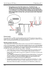
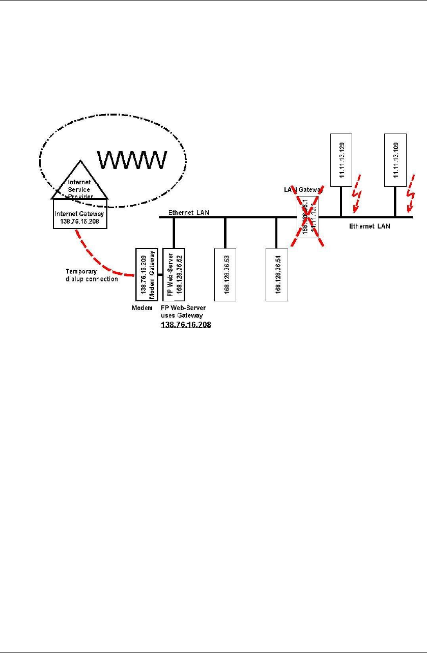
• During dial-up connection. Both stations (e.g. 168.128.36.53 and
168.128.36.54 without using the gateway) can communicate with the FP
Web-Server during the Internet dialup connection. The other stations (e.g.
11.11.13.129 and 11.11.13.109) that use the gateway may get communication
errors while Internet dialup is active. This is valid for all connection modes of
TCP communication, e.g. http, email, port communication and configuration
(Telnet, FTP).
Blocked emails
Some email ISPs, e.g. GMX, may block sending emails if the PLC sends too many emails or
emails are sent in quick succession. No official documentation or explanation could be found at
GMX. It can be assumed that GMX blocks sending 'swamp mail'.
Modem connection and setup
The FP Web-Server's dial-out (PPP-Client) function is set up for RTS/CTS handshake (pin 7
and 8 of the 9-pin connector). The following two paragraphs describe how to setup the modem
to also support RTS/CTS handshake. Only if the connected modem cannot support RTS/CTS
handshake should pin 7 be bridged to pin 8. However, this is not recommended and should only
be used with a slow modem baud rate (max. 9600 or 19200 bps).
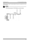
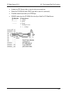
• The FP Web-Server firmware is designed for a FP Modem-EU connected to its 9-pin
port for Internet dialup. For this a 1:1 9-pin RS232C cable (standard computer to
modem cable) can be used to connect the FP Modem-EU to the 9-pin connector of the
FP Web-Server.
The FP Web-Server assumes the FP Modem-EU factory default settings. To make sure
that the FP Modem-EU has factory settings, please use a terminal program on your
computer and enter the command AT&F&W. Please also make sure that all DIP
switches of the FP Modem-EU are set to the OFF position!
• If a standard computer modem is to be used it can also be connected by a 1:1 9-pin
RS232C cable (standard computer to modem cable) to the 9-pin connector of the FP
Web-Server. Before the modem is connected to the FP Web-Server, please use a