


151
[Connections and Settings in Torque Control Mode]
Connections and Settings in
Torque Control Mode
Parameters for Speed Control
52 –2047
– 2047
[0]
0.3mVVelocity
command
offset
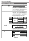
• This parameter adjusts offset of external analog speed command system
including the host device.
• Offset volume will be approximately 0.3mV per a set value “1”.
• To adjust offset, there are 2 ways of (1) manual adjustment and (2) auto
-
matic adjustment.
1) Manual adjustment
• When you make offset adjustment with the driver only:
Using this parameter, set a value that prevents the motor from rotat-
ing, after you have correctly input 0V in torque command input
(SPR/TRQR) (or connected to signal ground).
• When the host device establishes a position loop:
With servo locked, using this parameter, set a value so that deviation
pulse will be zero.
2) Automatic Adjustment
• For details on operating instructions in automatic offset adjustment
mode, refer to “Details of Execution Display of Auxiliary Function
Mode” of Preparations volume on page 66.
• When you execute automatic offset adjustment, result will be reflec-
ted in this parameter Pr52.
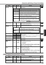
Parameter
No.
Setting
range
Parameter Name Unit Function/Description
Default setting is shown by [
]
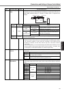
56
–20000
– 20000
[0]
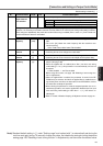
r/min4th internal
speed
The parameter directly sets the 1st to 4th speed of internal command
speed of when setting of internal speed has been enabled with the para
-
meter “speed setting internal/external switching” (Pr05), to Pr53 to Pr56
,
respectively, in the unit of [r/min].
<Caution>
Polarity of settings shows that of internal command speed.
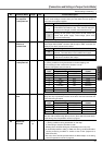
Pr56 is a value of speed limits in torque control mode.
You should set this parameter in a range of rotational speeds of the
motor to be used.
+
–
CCW direction viewed from the edge of axis for (+) command
CW direction viewed from the edge of axis for (-) command
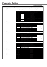
0 – 500
[300]
r/min
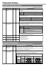
57 JOG speed set up
The parameter directly sets JOG speed in JOG run in “motor trial run
mode” in terms of [r/min].
For details on JOG function, refer to “Trial Run (JOG)” of Preparations vol
-
ume on page 68.
5D 0 – 1 –Torque command
input inversion
The parameter inverts polarity of the torque command input signa
l
(TRQR: CN X5 14-pin).
In speed/torque switching mode (when Pr02 is 5), torque command inpu
t
under torque control will be 16-pin of the connector CN X5.
Direction of Generation of Motor Torque
CCW direction viewed from the edge of axis for (+) command
CW direction viewed from the edge of axis for (+) command
Setting value
[0]
1
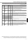
5C 10 – 100
[30]
0.1V/
100%
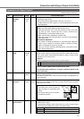
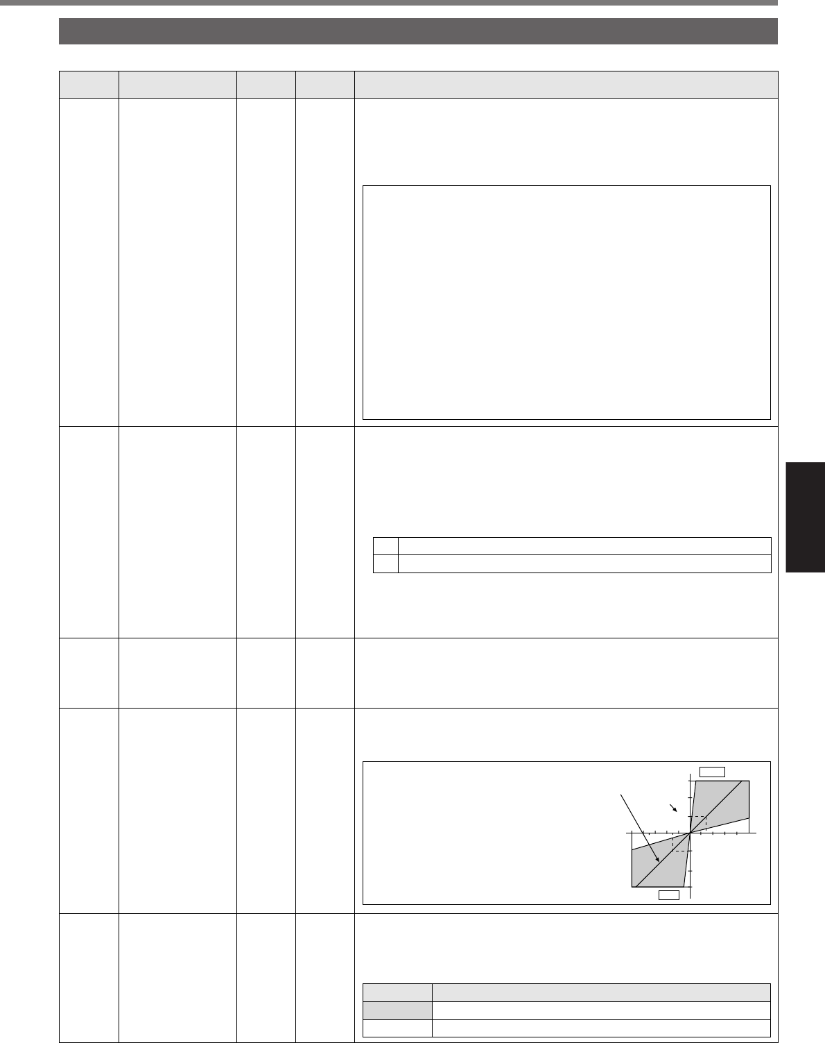
Torque command
input gain
The parameter sets a relationship between voltage applied to the torque
command input (TRQR: CN X5 14-pin) in torque control mode and gener
-
ated torque of the motor.
• Setting is in the unit of [0.1V/100%]
and used to set a value of input vol-
tage necessary for calculating rated
torque.
• At a factory setting of 30, the relation-
ship will be 3V/100%.
Rated
Torque
Torque
Setting of
Shipment
Time
Command
Input Voltage
2
-2-4-6-8-10V
100
100
200
300[%]
200
300[%]
46810V
CW
CCW