


134
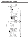
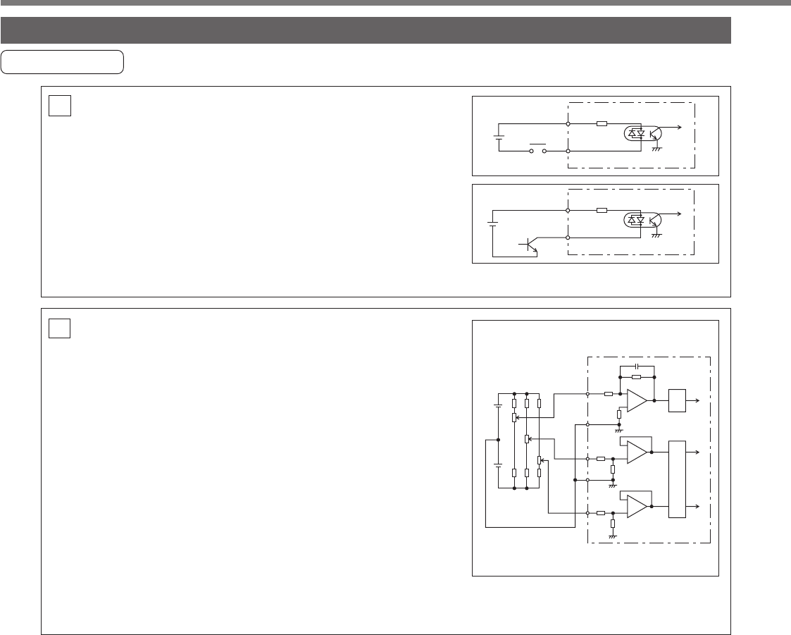
AI Analogue Command Input
• There are three analogue command inputs of SPR/RTQR
(14 pins), CCWTL (16 pins) and CWTL (18 pins).
• The maximum permissible input voltage is ±10V. For the
input impedance of these inputs, see the right figure.
• If you make a simplified circuit comprising a variable re-
sistor (VR) and resistor (R), refer to the right figure.
When the variable range of each input is -10V to +10V,
the VR should be a B type resistor of 2kΩ (min.1/2W).
The R should be 200Ω (min.1/2W).
• The A/D converters for these inputs should have the fol-
lowing resolution.
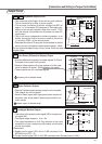
+
12V
SPR/TRQR
CCWTL
CWTL
R
14
20kΩ
10kΩ
GND
GND
10kΩ
10kΩ
10kΩ
ADC
1
ADC
2
15
16
17
18
R
VR
-12V
+
-
+
-
+
-
Interface Circuit
Input Circuit
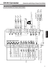
CN X5 Connector
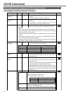
SI Connecting to
sequence input signals
• Connect to a contact of switch and relay, or a transistor
of an open collector output.
• Use a switch or relay for micro current so that insufficient
contact can be avoided.
• Lower limit of the power supply (12 to 24V) should not be
less than 11.4V in order to secure the appropriate level
of primary current of the photo coupler.
SI
1
2–24V
7
COM+4.7kΩ
Servo-ON or
other input
Relay
7 COM+4.7kΩ
1
2–24V
Servo-ON or
other input
1) ADC1 (SPR and TRQR) : 16 bits (including one bit for sign)
2) ADC2 (CCWTL and CWTL) : 10 bits (including one bit for sign)