


139
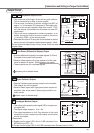
[Connections and Settings in Torque Control Mode]
Connections and Settings in
Torque Control Mode
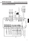
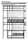
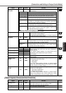
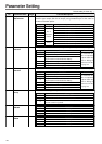
Output Signals (Others) and their Functions
Signal Pin No. Symbol Function I/F circu
it
Zero speed
detection
Torque in-limit
In-position/
At-speed
A-phase output
B-phase output
Z-phase output
Z-phase output
Speed monitor
output
Torque monitor
output
12
40
39
38
21
22
48
49
23
24
19
43
(17)
42
(17)
ZSP
TLC
COIN +
COIN –
OA +
OA –
OB +
OB –
OZ +
OZ –
CZ
SP
(GND)
IM
(GND)
SO2
page 13
5
SO2
page 13
5
SO1
page 13
5
PO1
page 13
5
PO2
page 13
5
AO
page 13
5
AO
page 13
5
• Signal which is selected at Pr0A (ZSP Output Selection) will
be turned on.
• Signal which is selected by Pr09 (TLC Output Selection) will
be turned ON. Factory-setting: 0
•
See the above ZSP signal for the set-up of Pr09 and functions.
• Function changes at control mode.
• Provides differential outputs of the encoder signals (A, B
and Z phases) that come from the driver (equivalent to
RS422 signals).
• The logical relation between A and B phases can be
selected by Pr45 (Output Pulse Logic Inversion).
• Not insulated
• Z-phase signal output in an open collector (not insulated)
• Not insulated
• Outputs the motor speed, or voltage in proportion to the
commanded speed with polarity.
+ : CCW rotation
– : CW rotation
• Use Pr07 (Speed Monitor Selection) to switch between
actual and commanded speed, and to define the relation
between speed and output voltage.
• Outputs the output torque, or voltage in proportion to the
position error with polarity.
+ : Fgenerating CCW-torque
– : Fgenerating CW-torque
• Use Pr08 (Torque Monitor Selection) to switch between
torque and positional error, and to define the relation
between torque/positional error and output voltage.
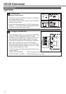
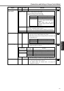
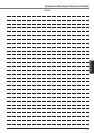
Pr0A value
0
1
(Factory-setting)
2*
3*
4*
5*
Function
Output(transistor) turns ON during the In-toque limiting.
Output(transistor) turns ON when the motor speed becomes
lower than that of the preset speed with Pr61(Zero speed).
Output(transistor) turns ON when either one of over-
regeneration, overload or battery warning is activated.
Output(transistor) turns ON when the over-regeneration (more
than 85% of permissible power of the internal regenerative
discharge resistor) warning is activated.
Output(transistor) turns ON when the overload (the effective torque is
more than 85% of the overload trip level) warning is activated.
Output(transistor) turns ON when the battery (the voltage of the
backup battery becomes lower than approx. 3.2V at the
encoder side) warning is activated.
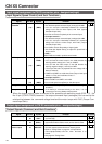
Position
Speed and
torque
• In-position output
• Output(transistor) turns ON when the position error is below
the preset value by Pr60 (In-Position Range).
• At-speed output
• Output(transistor) turns ON when the motor speed reaches
the preset value by Pr62 (At-Speed ).
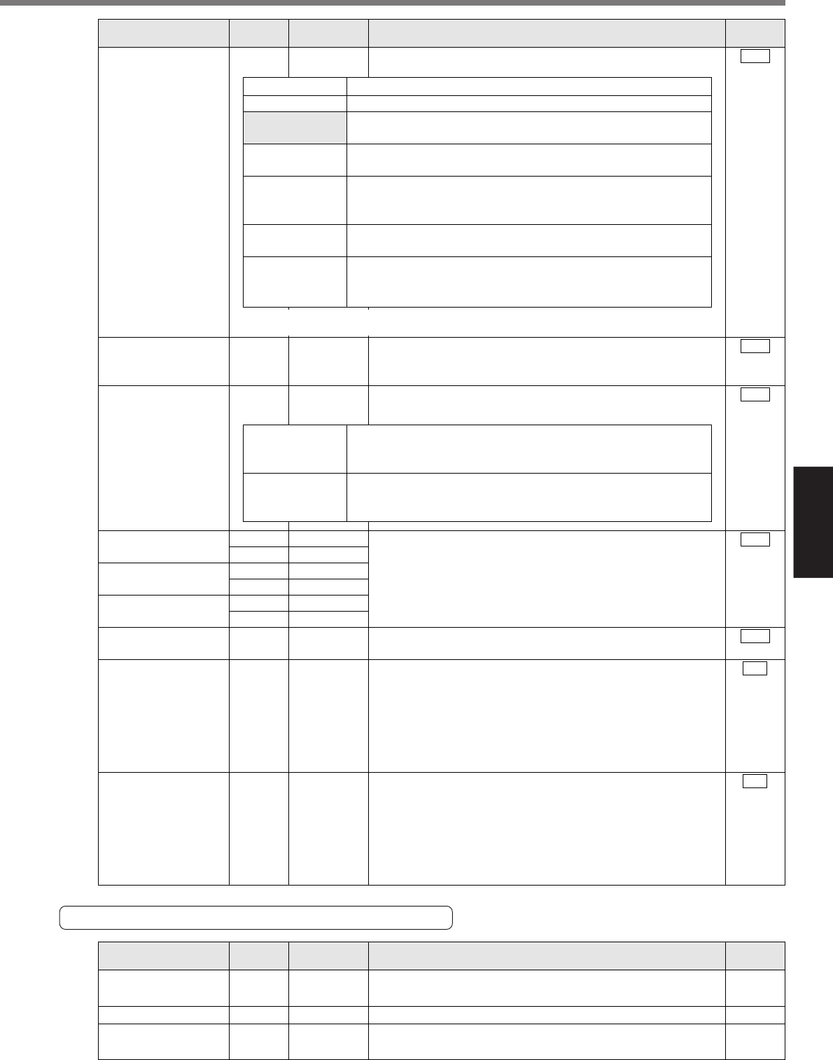
Signal Pin No. Symbol Function I/F circu
it
Signal ground
Frame ground
(Not in use)
13, 15
17, 25
50
1, 2, 20
46, 47
GND
FG
–
–
–
–
• Signal ground in the driver
• Internally isolated from the control power (COM -).
• Internally connected to the earth terminal.
• No connections should be made.
* When the setting is a value between 2 and 5, the output transistor will be turned on
for at least 1 second upon detecting an alarm condition.