


154
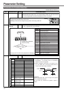
Parameter Setting
Parameter
No.
Setting
range
Parameter Name Unit Function/Description
Default setting is shown by [
]
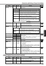
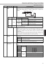
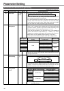
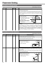
6A 0 – 100
[0]
2msMechanical brake
delay at
motor standstill
The parameter sets time till non-energization of motor (servo free) afte
r
the brake release signal (BRK-OFF) turns off (brake retained), at Serve
Off while the motor stops.
See also “Serve On/Off Operation When the Motor Stops” of the timing
chart of Preparations volume on page 43.
• In order to prevent minor
movement/drop of the motor
(work) due to operation de-
lay time of the brake (tb):
Setting of Pr6A
>
tb.
• See “Serve On/Off Operation
When the Motor Stops” of
the timing chart on page 42.
ON
SRV-ON
BRK-OFF
Actual Brake
Motor Energized
Release
OFF
Retention
Release
Energization
Retention
Non-
energization
Pr6A
tb
=
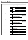
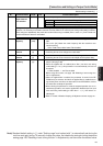
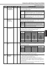
6B 0 – 100
[0]
2msMechanical brake
delay at
motor in motion
Unlike Pr6A, the parameter sets time till brake release signal (BRK-OFF
)
turns off (brake retained) after motor non-energization (servo-free), at Ser
-
vo off while the motor is rotating.
See also “Serve On/Off Operation When the Motor Stops” of the timing
chart of Preparations volume on page 42.
• This should be set to prevent de-
terioration of the brake due to
revolutions of the motor.
• At Servo off while the motor is ro-
tating, time tb in the right figure
will be either set time of Pr6B or
time till the motor rotational
speed falls below approximately
30r/min, whichever is smaller.
• See “Serve On/Off Operation When the Motor is
Rotating” of the timing chart of on page 43.
tb
ON
SRV-ON
BRK-OFF
Motor Speed
Release
OFF
Retention
Motor Energized
Energization
Non-
energization
30 r/min
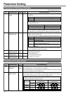
6D
0
–
32767
[35]
2msMain power-off
detection time
The parameter sets time to detect shut-off when shut-off of main powe
r
supply continues.
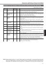
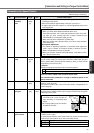
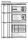
6C 0 – 3 –External
regenerative
resister set up
This parameter is set depending on whether to use regeneration resis
-
tance built in the driver, or to provide a regeneration resistance in the ex
-
ternal (connect between RB1 and RB2 of connector CN X 2 in types A to
D, and between terminal blocks P and B2 in types E - G).
<Request>
When you use an external regeneration, you must install external safe
-
guards such as a temperature fuse, etc.
Otherwise, as protection of regeneration resistance would be lost, causing
abnormal heat generation and burnout.
<Caution>
Be careful not to touch an external regeneration resistance.
While you are using an external resistance, it may become hot and scald
you. For type A, only external regeneration resistance is used.
Regeneration
Resistance to Use
Built-in resistance
External resistance
Built-in resistance
External resistance
Protection against Regeneration
Resistance Overload
According to built-in resistance, (about
1% duty) protection against regenera-
tion resistance overload works.
This is activated with operating limits of
the external resistance at 10% duty.
This is activated with operating limits of
the external resistance at 100% duty.
Regeneration resistance does not
work, and a built-in condenser accom-
modates all regenerated power.
Setting
value
[0]
1
2
3