


138
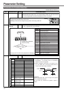
CN X5 Connector
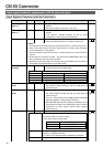
Input signal assignment to CN X5 connector pins - designation(logic)
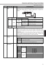
Input Signals (Speed Control) and their Functions
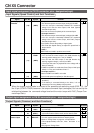
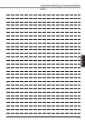
Output signal assignment to CN X5 connector pins - designation(logic)
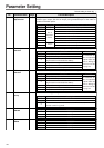
Output Signals (Common) and their Functions
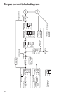
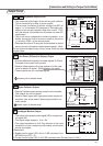
* When the torque control mode is selected at the speed/torque switching mode (Pr02 = 5), the
No.16 pin (CCWTL/TRQR) becomes the torque command input (analogue). You can set-up the
relationship between the command voltage level and the motor torque with Pr5C (Torque Com-
mand Input Gain).
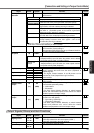
Signal Pin No. Symbol Function I/F circu
it
Speed (torque)
command
CCW torque limit
CW torque limit
14
(15)
16
(17)
18
(17)
SPR/TRQR
(GND)
CCWTL/
TRQR*
(GND)
CWTL
(GND)
AI
page 13
4
AI
page 13
4
< At speed control >
• This becomes speed command input (analogue) 0–±10V
• You can set-up the relationship between the command
voltage level and the motor speed, with Pr50 (Speed
Command Input Gain) .
• Use Pr51 to inverse the polarity of the command input.
< At torque control >*
• This becomes torque command input (analogue) 0–±10V
• You can set-up the relationship between the command
voltage level and the motor torque, with Pr5C (Torque
Command Input Gain) .
• Use Pr5D to inverse the polarity of input signals.
• Use Pr56 (4th Speed Set-up) to adjust the speed limit in
torque control.
< Note >
SPR/TRQR are invalid in position control mode.
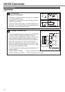
< At speed and position control >
• You can limit the motor torque in the CCW direction by
entering positive voltage (0 to +10V) to CCWTL.
• You can limit the motor torque in the CW direction by
entering negative voltage (-10 to 0V) to CWTL.
• The torque limit value is proportional to the voltage with a
factor of 100%/3V.
• CCWTL and CWTL are valid when Pr03 (Torque Limit Input
Inhibit) = 0. They are invalid when Pr03 = 1.
< At torque control >*
• Both of CCWTL and CWTL are invalid.
• Use the 4th speed set-up(Pr56) to limit the speed.
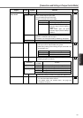
Battery +
Battery -
44
45
BATT +
BATT -
–
• Connect a backup battery for absolute encoder (pole-
sensitive !).
• If the battery is connected directly to the driver, it is not
necessary to connect a battery to this terminal.
Signal Pin No. Symbol Function I/F circu
it
Servo alarm output
Servo-ready output
Mechanical brake
release output
37
36
35
34
11
10
ALM +
ALM –
S-RDY +
S-RDY -
BRK-OFF +
BRK-OFF –
SO1
page 13
5
SO1
page 13
5
SO1
page 13
5
• This output(transistor) turns OFF, when the driver detects
and error(trip).
• This output(transistor) turns ON, when the main power is
on(for both the driver and the motor) and no alarm is active.
•
This is used to release the electromagnetic brake of the motor.
• Turn the output transistor ON when releasing brake.
• Refer to “Timing Chart” on page 40, on Preparations.
• This output(transistor) turns ON , when the brake is re-
leased.
• See page 40 "Timing Chart".