


136
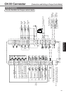
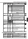
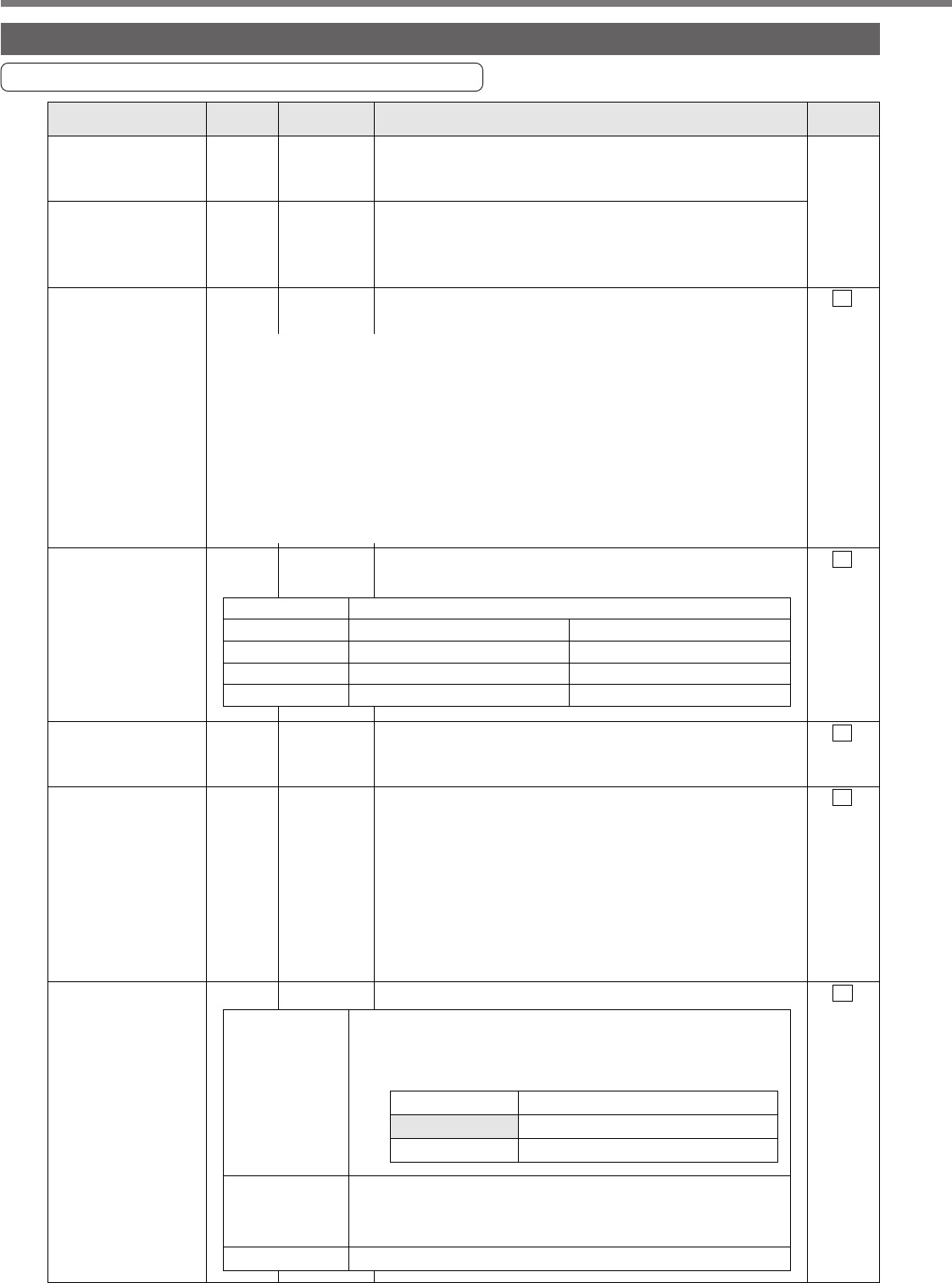
Input signal (common) assignment to CN X5 connector pins
Input Signals (Common) and their Functions
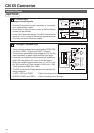
CN X5 Connector
Signal Pin No. Symbol Function I/F circu
it
Control signal
power (+)
Control signal
power (–)
Servo-ON
Control mode
switching
CW overtravel
inhibit
CCW overtravel
inhibit
Counter clear
7
41
29
32
8
9
30
COM +
COM –
SRV-ON
C-MODE
CWL
CCWL
CL
–
SI
page 13
4
SI
page 13
4
SI
page 13
4
SI
page 13
4
SI
page 13
4
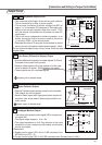
• Connect to (+) of an external power supply (12VDC to
24VDC).
• Use source voltage of 12V±10% – 24V±10%.
• Connect to (–) of an external power supply (12VDC to
24VDC).
• The required capacity depends on the I/O circuit
configuration. 0.5A or larger is recommended.
• When this signal is connected to COM-, the dynamic brake
will be released and the driver is enabled. (Servo-ON).
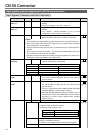
• When Pr02 (Control Mode Selection) = 3, 4 or 5, the control
mode is selected per the table below.
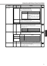
• If COM– is opened when the movable part of the machine
has moved to CW exceeding the limit, the motor does not
generate torque.
• If COM– is opened when the movable part of the machine
has moved CCW exceeding the limit, the motor does not
generate torque.
•
If you set 1 to Pr04 (Overtravel input inhibited invalid), CWL/CCWL
input will be disabled. A factory setting is Disable (1).
• With Pr66 (DB deactivate when driving is inhibited), you can
activate dynamic brake when CWL/CCWL input is enabled.
According to a factory setting, dynamic brake operates
(Pr66 is set to 0).
The function differs depending on the control mode.
<Notes>
1.
This signal becomes effective about two seconds after power on (see the Timing Chart).
2. Don't use this Servo-ON or Servo-OFF signal to turn on or off the motor. See page
46 "Dynamic Brake" in Preparations.
• Allow at least 50ms delay after the driver is enabled before any command input is
entered.
• By opening the connection to COM– , the driver will be disabled(Servo-OFF) and
the current flow to the motor will be inhibited.
• Operation of the dynamic brake and clearing action of the position error counter can
be selected using Pr69 (Sequence under Servo-OFF).
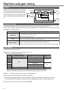
Pr02 value
3
4
5
open (1st)
Position control mode
Position control mode
Speed control mode
closed (2nd)
Connection with COM–
Speed control mode
Torque control mode
Torque control mode
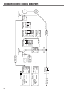
Position control
Speed control
Torque control
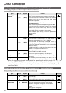
• Clears the position error counter.
Connect to COM– to clear the counter.
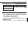
• Use Pr4D to select the clear mode.
• With speed setting of the 2nd selection input, you can set 4
speeds in combination with INH.
• For details, see Pr05 (Speed Set-Up Switching) description.
• Invalid
Pr4D value
0(Factory-setting)
1
Meaning
LEVEL
EDGE