


135
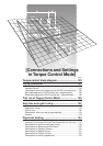
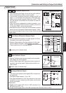
[Connections and Settings in Torque Control Mode]
Connections and Settings in
Torque Control Mode
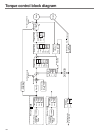
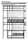
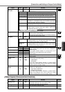
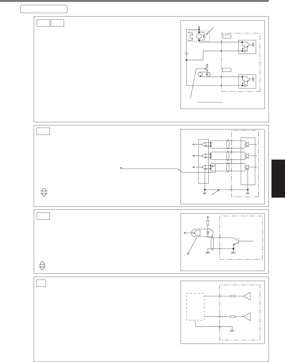
Sequence output circuit
• This comprises a Darlington driver with an open collector.
This is connected to a relay or photo coupler.
• There exists a collector-to-emitter voltage V
CE(SAT) of
approx. 1V at transistor ON, because of Darlington con-
nection of the out put transistor. Note that normal TTLIC
can't be directly connected since this does not meet VIL
requirement.
• This circuit has an independent emitter connection, or an
emitter connection that is commonly used as the minus
(–) terminal (COM–) of the control power.
• Calculate the value of R using the formula below so as the
primary current of the photo coupler become approx. 10mA.
For the recommended primary current value, check the data sheet on the equipment and photo-
coupler used.
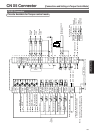
SO1 SO2
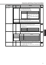
Line Driver (Differential Output) Output
• Provides differential outputs of encoder signals (A, B and
Z phases) that come from the scalar.
• Receive these signals with a line receivers. In this case,
install a resistor of approx. 330Ω between the inputs.
• These outputs are non-insulated signals.
PO1
Output Circuit
V
DC
12–24V
SO1
ALM+
or other signal
ALM–
or other signal
COM–41
ZSP, TLC
SO2
Install as per the fig. Shows
without fail
Maximum rating: 30V, 50m
A
V
DC
[V] — 2.5[V]
10
R
[kΩ] =
AM26LS32
or equivalent
AM26LS31
or equivalent
A
B
Z
22
21
OA+
OA-
OZ+
OZ-
OB+
OB-
48
23
25GND
24
49
Connect the signal
grounds between the controller and driver.
Open Collector Output
• Outputs Z-phase signals among those from the encoder.
The outputs are non-insulated.
• Receive these signal with high-speed photo coupler at
controller side, since these Z-phase signal width is nor-
mally narrow.
PO2
shows a pair of twisted wires.
shows a pair of twisted wires.
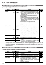
Analogue Monitor Output
• This output is the speed monitor signal (SP) or torque moni-
tor signal (IM).
• The signal range is approx. 0 to ± 9V.
• The output impedance is 1kΩ. Pay attention to the input
impedance of your measuring instruments and external
circuits connected.
<Resolution>
1) Speed monitor signal (SP): 8r/min./LSB calculated from
6V/3000r/min (Pr07 = 3)
2) Torque monitor signal (IM): 0.4%/LSB calculated from 3V/rated value (100%)
AO
43
1kΩ
1kΩ
SP
IM
42
GND
17
Measuring
instrument
or external
circuit
19
25
CZ
Maximum rating:
30V, 50mA
GND
H
igh-speed
p
hoto coupler
(
Equivalent to Toshiba TLP554)