About your projector
ENGLISH - 21
Preparation
■
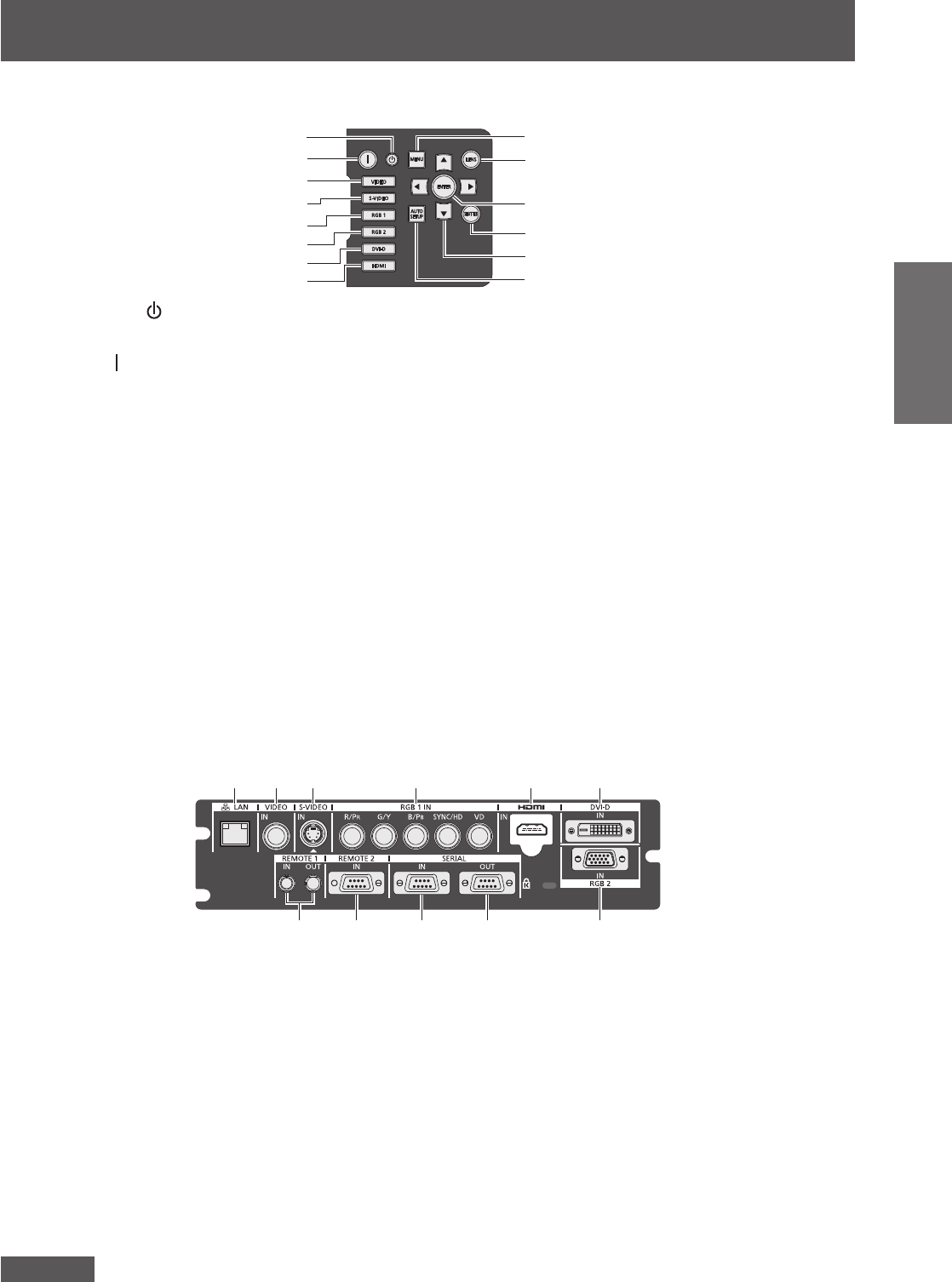
Control panel
(9)
(10)
(11)
(12)
(13)
(14)
(1)
(2)
(3)
(4)
(5)
(6)
(7)
(8)
(1)
Power standby <
> button
Sets the projector to the standby mode when the <MAIN
POWER> switch on the projector is set to <ON>.
(2)
Power on <
> button
Starts projection when the <MAIN POWER> switch on the
projector is set to <ON> when the power is switched off
(standby mode).
(3) <VIDEO> button
Switches to VIDEO input.
(4) <S-VIDEO> button
Switches to S-VIDEO input.
(5) <RGB1> button
Switches to RGB1 input.
(6) <RGB2> button
Switches to RGB2 input.
(7) <DVI-D> button
Switches to DVI-D input.
(8) <HDMI> button
Switches to HDMI input.
(9) <MENU> button
Displays and erases the main menu.
Returns to the previous screen when a sub-menu is
displayed.(
page 44)
If you press the <MENU> button on the control panel for
at least three seconds while the on-screen indication is off,
the on-screen display is turned on.
(10)<LENS> button
Adjusts the focus, zoom, and shift (position) of the lens.
(11) <ENTER> button
Determines and executes an item in the menu screen.
(12)<SHUTTER> button
Use to temporarily turn off the image.(
page 41)
(13)
selection buttons
Use to select items in the menu screen, change settings,
and adjust levels.
It is also used to enter [SECURITY] passwords.
(14)<AUTO SETUP> button
Automatically adjusts the image display position while
projecting the image.
[PROGRESS] is displayed on the screen while the image
is adjusted automatically.(
page 42)
■
Connecting terminals
(1) (2) (3) (4) (5) (6)
(7) (8) (9) (10) (11)
(1) <LAN> terminal
This is a terminal to connect to the network.
Used for control and monitoring. Image input through
network connections is not possible.
(2) <VIDEO IN> terminal
This is a terminal to input video signals.
(3) <S-VIDEO IN> terminal
This is a terminal to input S video signals.
(4) <RGB 1 IN> (<R/P
R
>, <G/Y>, <B/P
B
>, <SYNC/HD>,
<VD>) terminal
This is a terminal to input RGB signals or YC
B
C
R
/YP
B
P
R
signals.
(5) <HDMI IN> terminal
This is a terminal to input HDMI signals.
(6) <DVI-D IN> terminal
This is a terminal to input DVI-D signals.
(7) <REMOTE 1 IN> terminal / <REMOTE 1 OUT> terminal
These are the terminals to connect the remote control for
serial control when the system uses multiple projectors.
(8) <REMOTE 2 IN> terminal
This is a terminal to remotely control the projector using
the external control circuit.
(9) <SERIAL IN> terminal
This is a RS-232C compatible terminal to externally control
the projector by connecting a computer.
(10)<SERIAL OUT> terminal
This is a terminal to output the signal connected to the
serial input terminal.
(11) <RGB 2 IN> terminal
This is a terminal to input RGB signals or YC
B
C
R
/YP
B
P
R
signals.
Attention
z
When a LAN cable is directly connected to the projector, the network connection must be made indoors.


