


D-13615-A2-GB20-20 December 1996
Pin Assignments
Overview D-1. . . . . . . . . . . . . . . . . . . . . . . . . . . . . . . . . . . . . . . . . . . . . . . . . . . . . . . . . . . . . . . . . . . . . . . . . .
Network Connectors D-1. . . . . . . . . . . . . . . . . . . . . . . . . . . . . . . . . . . . . . . . . . . . . . . . . . . . . . . . . . . . . . . . .
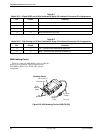
3600 Hubbing Device D-2. . . . . . . . . . . . . . . . . . . . . . . . . . . . . . . . . . . . . . . . . . . . . . . . . . . . . . . . . . . . .
DTE Connectors D-4. . . . . . . . . . . . . . . . . . . . . . . . . . . . . . . . . . . . . . . . . . . . . . . . . . . . . . . . . . . . . . . . . . . .
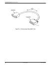
Crossover Cables D-8. . . . . . . . . . . . . . . . . . . . . . . . . . . . . . . . . . . . . . . . . . . . . . . . . . . . . . . . . . . . . . . . .
Overview
Pin
assignments for the 3615 Series DSU connectors
and interfaces are included here. Refer to them as needed.
Refer to the
COMSPHERE 3000 Series Carrier
,
Installation Manual for additional pin assignments.
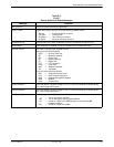
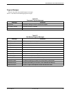
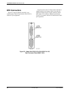
Network Connectors
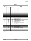
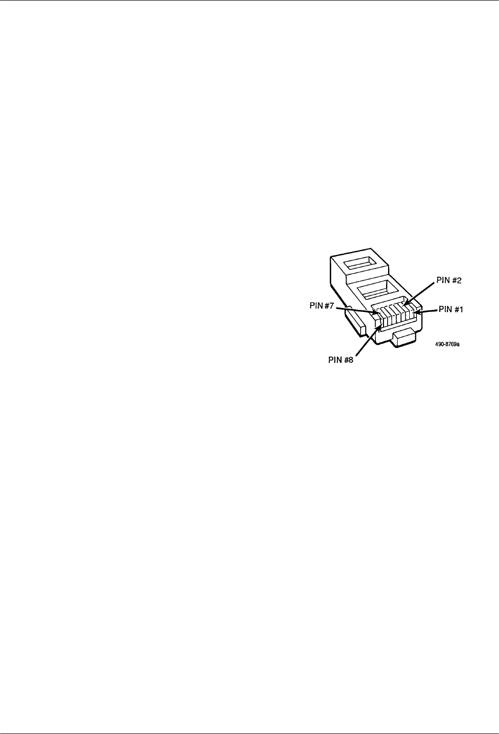
Figure
D-1 shows the Model 3615 DSU’
s digital
network connector, which is used for DDS and the 4-wire
Switched 56 kbps connection. Table D-1 provides its pin
assignments. T
able D-2 provides the network connector
pin assignments used for the V
.32 and 2-wire Switched 56
DBM, which uses a 6-pin jack (not shown in any figure).
Figure D-1. Digital Network Connector
D