


COMSPHERE DualFlow Data Service Units
3-2 December 1996 3615-A2-GB20-20
Before
Y
ou Begin
The COMSPHERE 3000 Series Carrier should already
be installed properly and be operational, with a
functioning shared diagnostic control panel (SDCP). An
SDCP (installed in the carrier) is required for installation
and maintenance of the Model 3616 DSU. For installation
information, see the
COMSPHERE 3000 Series Carrier
,
Installation Manual.
A fan module may also be needed to dissipate heat.
Refer to the Fan Module Installation
section in Chapter 3
of the
COMSPHERE 3000 Series Carrier
, Installation
Manual to determine whether a fan is required.
The distance between your DTE and the DSU must be
within EIA-232-D/V.24 or V.35 limits.
• For the EIA-232 connector, the maximum
recommended distance is 50 feet. If operating at
56 kbps the maximum distance is 34 feet for
shielded cable, and 68 feet for unshielded cable.
When a Switched 56 DBM is installed, ensure that
the effective shunt capacitance of the circuit
(measured at the DSU and including the
capacitance of the cable and the DTE) does not
exceed 1250 picofarads.
• For the V
.35 connector
, the recommended
maximum distance between a DTE and DSU is
nominally 1000 feet.
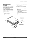
Contact the telephone company to coordinate your
installation before connecting the DSU to the DDS,
Switched 56 kbps, or dial network. The DSU can only
operate at the data rate for which access to the DDS or
dial network is provided.
Refer to the notice at the fr
ont of
this guide to ensur
e compliance with FCC, Bell Canada,
and Canadian DOC rules.
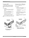
How to Change
Hardware Straps
HANDLING
PRECAUTIONS
FOR
STA
TIC-SENSITIVE DEVICES
This product is designed to protect
sensitive components from damage
due to electrostatic discharge (ESD)
during normal operation. When
performing installation procedures,
however, take proper static control
precautions to prevent damage to
equipment. If you are not sure of the
proper static control precautions,
contact your near
est sales or service
representative.
The Model 3616 DSU has several hardware straps that
control the permissive or programmable connection when
a DBM is installed, the T
est Mode Indication leads, and
the external interface leads (used with a –
48 Vdc Central
Office Power Unit).
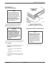
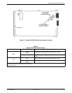
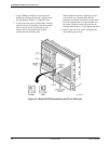
Refer to Figure 3-1 to locate the switch and jumper
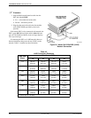
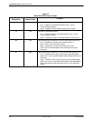
locations. If a V.32 DBM is installed, refer to Table 3-1 to
determine which switch needs to be changed, if any
. Refer
to Table 3-2 to determine whether these jumper straps
need to be changed.