


Installing the Model 3615 DualFlow DSU
2-33615-A2-GB20-20 December 1996
496-14499-01
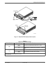
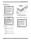
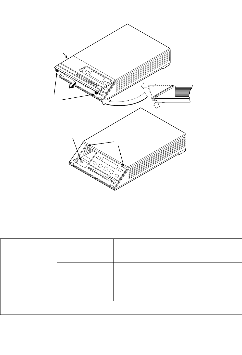
SWITCH 1
HINGE TAB
LOCATIONS
FRONT BEZEL
COMSPHERE 3615
SNAP
TABS
Figure 2-1. Model 3615 DSU Hardware Switch Location
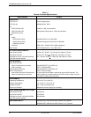
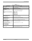
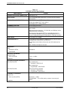
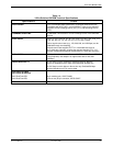
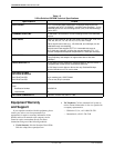
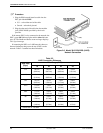
Table 2-1
Model 3615 DSU Switch Settings
Switch Position Switch Setting Function
S1-1
ON
(default)
Permissive V.32 DBM transmit output level of –9 dBm
S1-1
Off Programmable V.32 DBM transmit level between –12 dBm and
0 dBm
ON Frame ground (FG) connected to signal ground (SG)
S1-2
Off
(default)
FG connected to SG through 100 ohm resistor
ON is to the rear as you face the front of the DSU.
Off is to the front.