


Operating the DSU
4-193615-A2-GB20-20 December 1996
Control Branch
The Control (Ctrl) branch allows you to enable or
disable the DSU’s transmitter
, as well as the DBM’
s, and
to display or change the status of the general purpose
external DTE leads. A DBM can be disabled if it is
addr
essed fr
om the Remote branch.
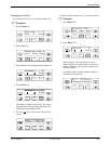
Transmitter Control
The Transmitter Control (TxCtl
) selection allows you
to enable or disable the DSU’
s or DBM’
s transmitter
(DDS core).
When the DSU transmitter is disabled, the following is
possible:
•
When a DSU is disabled, it responds to tests.
Aborting a test clears the test but the unit remains
disabled.
•
A DSU in test clears the test when a disable (or
enable) command is received.
• If an enable command is executed to a control from
the NMS or the local DCP
, all disabled tributaries
are enabled; all tributaries in test are restored to
Data mode.
When the local DBM is disabled, the DBM does not
originate or answer any calls until enabled.
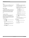
LEDs
The LEDs selection is only available from the Local
branch. This selection allows you to monitor the port at
any given time. When selected, the port’
s lead activity is
reflected in the DCP circuit designation status indicators
(TXD, RXD, etc.) on the faceplate of the Model 3616
DSU, or on the DCP of the Model 3615 DSU.
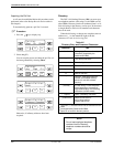
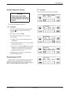
External Leads
The External Leads (ExtL
) selection allows you to
display the state of
four general-purpose leads on the
EIA-232-D/V.24 port interface: Pins 12 and 13 for output
(control leads) and Pins 19 and 23 for input (alarm leads).
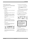
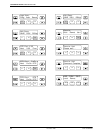
When the configuration option Ext Leads (External
Leads) is set to ExtLd (DBM Port option set), you can
change the state of the two output leads from the DCP or
NMS. When
CCN by EL
(CCN by External Leads) is
enabled (DBM Port option set), the control DSU reports
changes in the four leads to the NMS as part of its health
and status poll response.
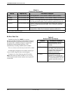
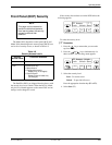
T
able 4-7 describes the meaning of the state of each
input or output lead.
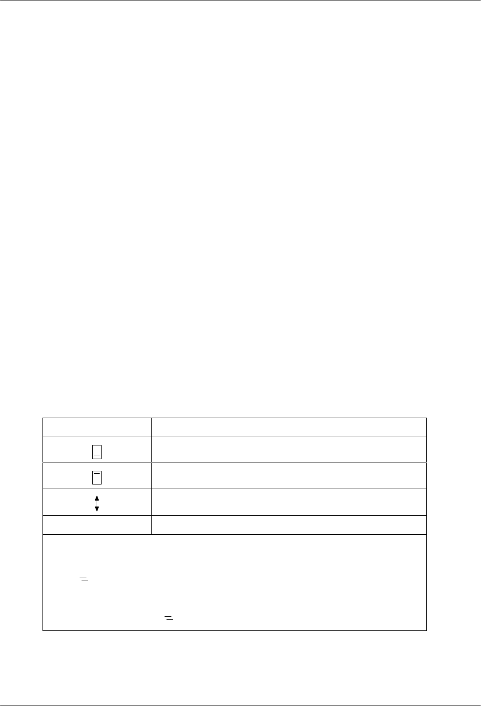
Table 4-7
Lead States
Symbol Meaning
Off (below text line)
ON (above text line)
Changing
?
Indicates an illegal value
NOTES:
Input leads A and B:
Off (
) when voltage on lead is less than +.8V.
ON (
) when voltage on lead is more than +2.2V.
Output leads are either ON or Off:
When output is set to Off (
), –12V is applied to lead.
When output is set to ON (
), +12V is applied to lead.