AT Commands and S-Registers
4-133821-A2-GB20-30 February 1998
Table 4-1
(11 of 13)
3821
Plus
AT Commands
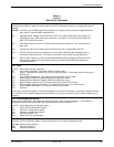
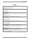
%C
n
– MNP5 Data Compression
Determines if the modem uses MNP Class 5 data compression. It can be set independently of V.42bis data compression.
Online changes do not take effect until a disconnect occurs.
%C, %C0 Disable.
%C1 Enable.
+FCLASS=
n
– Service Class Selection
Normally set by fax software, Service Class Selection determines the fax protocol. The command is sent to the modem in
the format +FCLASS=
n
, where
n
can be set to one of three values:
0 = Data
1 = Class 1 Fax (EIA 578)
2 = Class 2 Fax (EIA/TIA SP-2388 dated 20 August 1990)
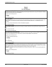
In the format +FCLASS?, the +FCLASS command returns the current Service Class: 0, 1, or 2. In the format
+FCLASS=?, the +FCLASS command returns the Service Classes available: 0,1, 2.
NOTE: Other fax commands supported by the 3821
Plus
modem are not documented in this manual because they are
not normally issued by the user. They follow the EIA 578 and EIA/TIA SP-2388 specifications.
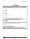
\A
n
–Maximum Frame Size
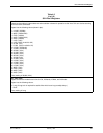
Sets the maximum frame size for V.42 and MNP. For MNP, the minimum value is 64; if a smaller value is specified, it will
default to 64.
\A, \A0 64
\A1 128
\A2 192
\A3 256
\A4 32
\A5 16
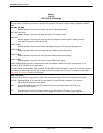
\C
n
– Error Control Negotiate Buffer
Determines if the answering modem buffers the data that it received from the remote modem during an interval in which
the modem attempts to establish a connection using error control. Online changes to this configuration option do not take
effect until a disconnect occurs.
\C, \C0 Disable.
\C1 Enable.
\C2 Disable and Switch. Modem automatically switches to Buffer mode if it receives an error control fallback
character (an ASCII carriage return see %A command) during error control negotiation.
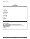
\D
n
– CTS Control
Clear-to-Send (CTS) is a signal from the modem to the DTE indicating that it can accept data from the DTE.
\D, \D0 Forced On. Forces CTS to always ON.
\D1 Standard RS232.
\D2 Wink When Disconnect. CTS is turned Off for 1 to 2 seconds upon a disconnect.
\D3 Follows DTR. The state of CTS follows the state of DTR.
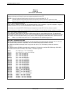
\G
n
– Modem to Modem Flow Control
If a modem’s buffers begin to fill due to data it is receiving from the remote modem, but is not passing the data on to the
DTE, it can issue flow control messages to the remote modem. This only applies during Buffer mode connections where
the remote modem also has modem-to-modem flow control enabled. If Error Control mode is enabled, flow control
between the modems will happen automatically, regardless of the setting of this configuration option.
\G, \G0 Disable.
\G1 Enable.


