


Standards Compliance for SNMP Traps
D-3
7112-A2-GB20-20
March 1998
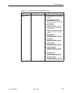
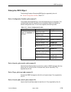
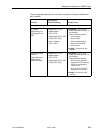
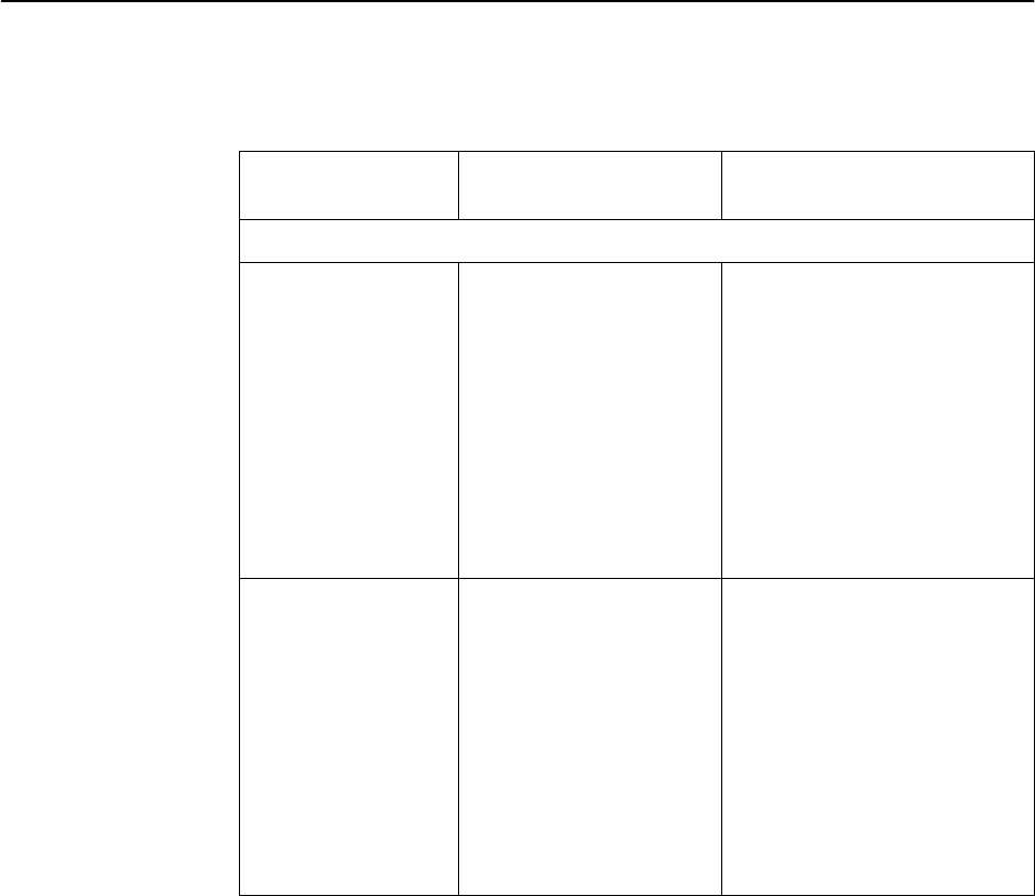
The following table describes the conditions that define linkUp and linkDown for
each interface:
Interface
linkUp/Down
Variable-Bindings
Possible Cause
Physical Sublayer – Represented by the entry in the MIB II Interfaces Table.
T1 network
(Supported by the
media-specific ds1
MIB.)
H ifIndex (RFC 1573)
H ifAdminStatus
(RFC 1573)
H ifOperStatus (RFC 1573)
H ifType (RFC 1573)
H dsx1LineStatus
(RFC 1406)
H linkDown – One or more
alarm conditions are active on
the interface.
Alarm conditions include:
– Loss of Signal
– Out of Frame
– Alarm Indication Signal
– Excessive Error Rate
– Yellow Alarm
H linkUp – No alarms on the
interface.
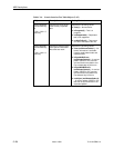
Synchronous User
Data Port
(Supported by the
media-specific
RS232-Like MIB.)
H ifIndex (RFC 1573)
H ifAdminStatus
(RFC 1573)
H ifOperStatus (RFC 1573)
H ifType (RFC 1573)
H linkDown – One or more
alarm conditions are active on
the interface.
Alarm conditions include:
– DTR Off (only if the DTE
supports the DTR lead and
the port is configured to
monitor DTR.
– RTS Off (only if the DTE
supports the RTS lead).
H linkUp – No alarms on the
interface.