


Monitoring the DSU/CSU
6-2
7112-A2-GB20-20
March 1998
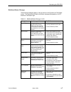
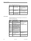
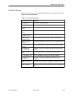
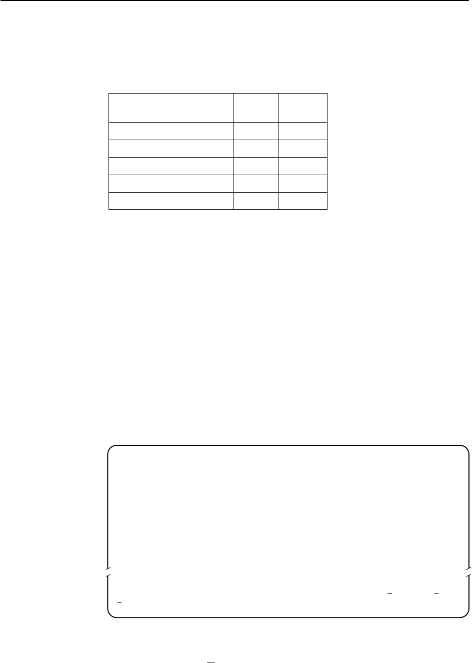
Table 6-1 shows the available indicators of alarm conditions on the network
interface and the User Data port.
Table 6-1. Alarm Indicator Locations
Alarm Condition
Status
Screen
Network
LED
Loss of Signal (LOS) Y SIG
Out of Frame (OOF) Y OOF
Alarm Indication Signal (AIS) Y ALARM
Excessive Error Rate (EER) Y EER
Yellow Y ALARM
DSU/CSU LEDs
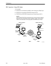
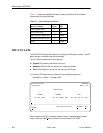
The DSU/CSU LEDs can be viewed on the Display LEDs Status screen. This ATI
status screen is available locally and remotely.
The 12 LEDs are organized in three groups:
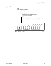
H System LEDs display the status of the unit.
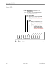
H Network LEDs provide the status of the network interface.
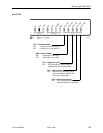
H Port LEDs display the activity on the user data (DTE) port.
To view the LED status screen, follow this menu selection sequence:
Main Menu
→
Status
→
Display LEDs
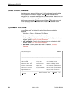
main/status/leds PARADYNE
Device Name: Model: 7112
DISPLAY LEDS
SYSTEM NETWORK PORT
OK FAIL TEST SIG OOF ALARM EER TXD RXD RTS CTS DTR
––––––––––––––––––––––––––––––––––––––––––––––––––––––––––––––––––––––––––––––––
ESC for previous menu M
ainMenu Exit
R
efresh
When viewed via the ATI, the status display screen is updated approximately
every 5 seconds. Use R
efresh to obtain a current status of all LEDs.