


Index
IN-3
7112-A2-GB20-20 March 1998
N
navigating the screens, 2-4
network
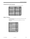
interface cable, E-2
interface options, A-3
interface port location, 1-4
LEDs, 6-4
tests, 7-3
NMS
SNMP access, 4-7
SNMP connectivity, 5-1
SNMP security options, A-17
no test active status message, 6-9
O
objects for MIBs, C-1
OK, LED, 6-3
OOF (out of frame)
LED, 6-4
performance statistic, 6-12
status message, 6-7
options
configuration tables, A-1
configuration worksheets, B-1
P
package checklist.
See
Start-Up Instructions
Passed, status, 6-8
payload loopback (PLB), 7-4
performance statistics, 6-11
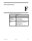
physical description of DSU/CSU, F-2
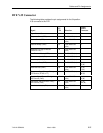
pin assignments, E-1
port, LEDs, 6-5
PORT (1–2) interface, technical specifications, F-2
power input, consumption, F-2
power input connector location, 1-4
power module, F-2
primary clock failed, status message, 6-7
primary clock source, A-3
Q
QRSS Test, GL-4
R
rear panel, 1-4
Refresh command, 6-6
remote line loopback , 7-6
remote send line loopback, 7-6
repeater loopback (RLB), 7-5
resetting
the access unit, COM port, 4-3
the DSU/CSU, default configuration options, 4-3
restoring, user interface access, 4-3
RFC 1643, object groups supported, C-20
RFCs, MIB descriptions, C-1
RJ48C network interface cable, E-2
router, management data, 5-2
routing information protocol.
See
RIP
RS-232-Like MIB, C-20
RTS, request to send LED, 6-5
RXD, received data LED, 6-5
S
safety instructions.
See
Start-Up Instructions
saving option changes, 3-3
screens, for user interface, 2-1– 2-6
security, 4-1
self-test results, 6-8
send FT1 sequence test, 7-11
Send Ones configuration option, A-9
send test pattern
data port, 7-11
network, 7-6
send V.54 sequence test, 7-10
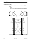
serial crossover cable, E-4
SIG, network signal LED, 6-4
SNMP
access, 4-6
features, 1-4
setup traps, 8-1
system entries, 3-1
traps, D-1
SNMP & communication, options, A-16
specifications, environmental, F-1
start-up
ATI, 2-1
instructions.
See
Document 7112-A2-GN10