


Customizing DSX-1-Compatible Units
4-5
7924-A2-GB20-30
October 1997
Making Changes in Switchpack Mode
When operating in Switchpack Mode, you can change configuration options by
moving switches on the board hardware.
To enable Switchpack Mode, refer to
Switching Between Terminal and
Switchpack Modes
in Chapter 3,
Using Terminal and Switchpack Modes.
" Procedure
Use electrostatic discharge (ESD) protection when handling the circuit board.
To open the unit and make changes while in Switchpack Mode:
1. Power down the unit and expose the circuit board by loosening the two
screws on the back panel of the unit and sliding off the cover.
2. Refer to the board layout illustration in Appendix C,
Switchpacks and
Jumpers
, to locate switchpack S1.
3. Place the switchpack in the correct position for each desired configuration
option. Definitions of switchpack positions are provided in Appendix C,
Switchpacks and Jumpers
.
For example, to change a unit’s card type from CO to CP, move switch 1 on
switchpack S1 to the OFF position.
4. Replace the cover and screws.
5. Power up the board to reset and enable the new configuration.
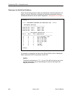
Displaying Switchpack Definitions
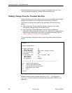
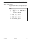
Enter 6 at the Config prompt to display the definition of each position in the
switchpack. Switchpack definitions are also listed in Appendix C,
Switchpacks
and Jumpers
.
Config→ 6
Switch pack definition: (OFF=0, ON=1)
1 – CO/CP OFF=CP, ON=CO
2 – B8ZS OFF/ON
3 – Dual/Single Loop Mode OFF=Dual, ON=Single
4 – Line Build Out Bit 0
5 – Line Build Out Bit 1
6 – Line Build Out Bit 2
7,8 – 00=Unframed, 01=D4
11=ESF
Config→