


Customizing DSX-1-Compatible Units
4-6
7924-A2-GB20-30
October 1997
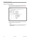
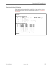
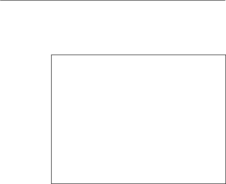
Displaying Line Build-Out Definitions
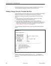
Enter 7 at the Config prompt to display the switchpack and board settings for line
build-out. Use this information to change the line build-out parameter manually.
(Switchpack definitions are also listed in Appendix C,
Switchpacks and Jumpers
.)
Config→ 7
***** SWITCHPACK SETTINGS FOR LINE BUILD OUT *******
Switchpack Settings
–––––––––––––––––––––––––––––––––––
Position #4 – Bit 0 OFF=0, ON=1
Position #5 – Bit 1 OFF=0, ON=1
Position #6 – Bit 2 OFF=0, ON=1
************ Switchpack Definitions ************
Bit 2 Bit 1 Bit 0 Application
–––––––––––––––––––––––––––––––––––––––––––––––
0 0 0 0 to 133 feet – 0dB
0 0 1 133 to 266 feet
0 1 0 266 to 399 feet
0 1 1 399 to 533 feet
1 0 0 533 to 655 feet
1 0 1 -7.5 dB
1 1 0 -15 dB
1 1 1 -22.5 dB
Config→
For example, to change the line build-out to 399 to 533 feet, while in Switchpack
Mode, set position 6 OFF and positions 4 and 5 ON.
NOTE:
The switch combinations for –7.5, –15, and –22.5 dB line build-out are not for
use with this product. Use of these settings will cause a weak signal and
degrade performance.