


Switchpacks and Jumpers
C-4
7924-A2-GB20-30October 1997
97-15524-0
1
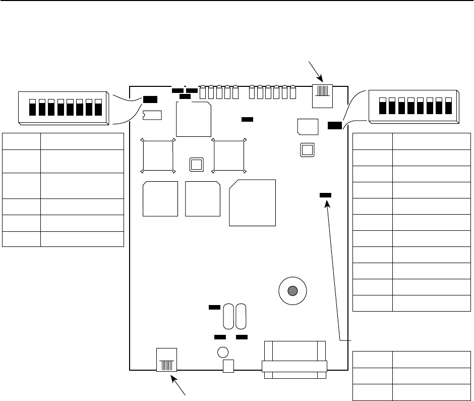
S1
S2
P8
V.35
Switchpack S1
Switchpack S2
Jumper P8
VT100 Terminal
Modular Jack
HDSL Line Jack
P4
P1 P2
P10
P11
P9
P5
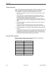
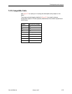
Position
1
2
3
4, 5
6, 7, 8
Settings*
OFF = CP
ON = CO
OFF = Loops A and B
ON = Loop A
unused
10 = Loop Clock
unused
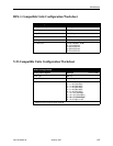
Position
1
2
3
4
5
6
7
8
Settings*
ON = 64 kbps
ON = 128 kbps
ON = 192 kbps
ON = 256 kbps
ON = 384 kbps
ON = 512 kbps
ON = 768 kbps
ON = 1024 kbps
All ON = 64 kbps
All OFF = 1536 kbps
Pins*
1-2
2-3
Settings*
Terminal Mode
Switchpack Mode
* Default in bold
123
123 321
12
123
123
123
321
678
ON
12345
678
ON
12345
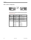
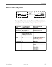
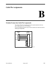
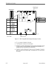
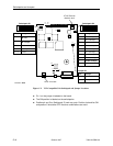
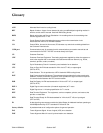
Figure C-2. V.35-Compatible Unit Switchpack and Jumper Locations
H Pin 1 on the jumper is labeled on the board.
H The ON position is labeled on the switchpacks.
H Positions 4 and 5 on Switchpack S1 work as a pair. Position 4 should be ON
and position 5 should be OFF. No other combinations are valid.