


Monitoring the Unit
6-6
7924-A2-GB20-30
October 1997
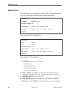
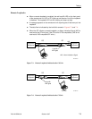
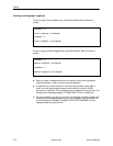
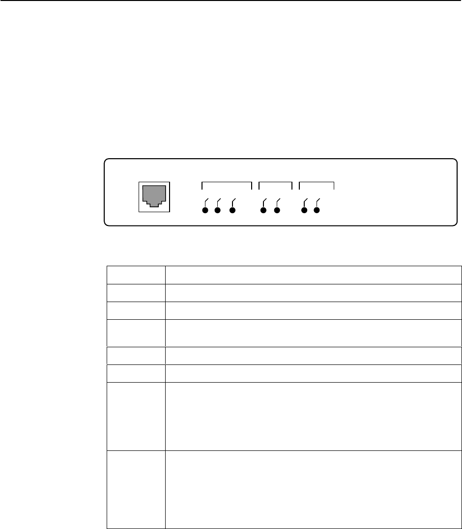
Front Panel LEDs
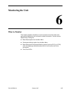
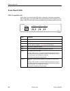
DSX-1-Compatible Unit
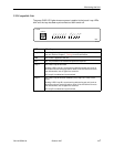
Upon power up, the first three LEDs blink in sequence, indicating a successful
start configuration. The green PWR LED lights whenever power is applied to the
board. Loop LEDs blink until the loop has been synchronized and then remain off.
TM
TERMINAL
T1 HDSL
Local
Remote
Loop Bk
PWR
FAIL
Loop A
Loop B
NETWORK SYSTEM HDSL
TM
7900
7900
97-15312
LED Meaning
Local ON: The local T1 interface has a loss of signal.
Remote ON: The remote T1 interface has a loss of signal.
Loop Bk ON: A loopback has been initiated for testing the equipment connected to
this unit. Refer to Chapter 7,
Testing
, for more information.
PWR ON: Power is applied to the unit.
FAIL ON: The processor has halted and repairs are required.
Loop A ON: HDSL Loop A has failed.
Blinking: HDSL Loop A is synchronizing with the far-end unit (such as
when the units are coming up after a reset). If the LED blinks for more
than 60 seconds, loss of signal has occurred.
Off: Loop A is enabled and synchronized.
Loop B ON: HDSL Loop B has been disabled (only Loop A is in use) or has
failed.
Blinking: HDSL Loop B is synchronizing with the far-end unit (such as
when the units are coming up after a reset). If the LED blinks for more
than 60 seconds, loss of signal has occurred.
Off: Loop B is enabled and synchronized.