


Cable Pin Assignments
B-4
7924-A2-GB20-30October 1997
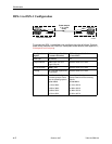
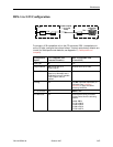
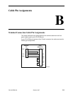
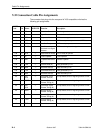
V.35 Connection Cable Pin Assignments
The connector that plugs into the rear panel of V.35-compatible units has the
following pin assignments.
CCITT
Code
Pin Name
Direction
DCE DTE
Function Description
101 A PG Protective Ground Machine ground
102 B SG Signal Ground Ground reference for all circuits
105 C RTS ← Request to Send DTE has message to send
106 D CTS → Clear to Send DCE is ready to accept and transmit DTE data
107 E DSR → Data Set Ready DCE is ready to operate
109 F RLSD → Data Channel
Received Line Signal
Detector
DCE is receiving a carrier signal
108 H DTR ← Data Receiver Ready DTE is ready to operate
141 L LL ← Local Loopback Local loopback
140 N RDL ← Loopback/Maintenan
ce
Remote loopback
103 P TXD ← Transmit Data (A) Data generated by DTE
104 R/D RXD → Received Data (A) Data received by DTE
103 S TXD ← Transmitted Data (B) Data generated by DTE
104 R RXD → Received Data (B) Data received by DTE
113 U EXT
CLK
← Transmitter Signal
Element Time (A)
To help detect center of signaling element on BA
115 V RSET → Receiver Signal
Element Timing (A)
To help detect center of signaling element on BB
113 W EXT
CLK
← Transmitter Signal
Element Timing (B)
To help detect center of signaling element on BA
115 X RSET → Receiver Signal
Element Timing (B)
To help detect center of signaling element on BB
114 Y TSET → Transmit Signal
Element Timing (A)
To help detect center of signaling element on BA
114 a TSET → Transmit Signal
Element Timing (B)
To help detect center of signaling element on BB
142 n TST → Test Indicator Reserved for test