


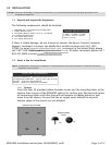
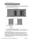
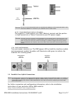

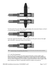
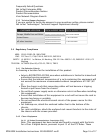
1.5.3.3 Connect Both Power Leads to a Fuse Panel
The negative (-) lead connects to a "Batt" (Battery) terminal and the positive
(+) lead connects to a "Return" terminal on your DC power supply.
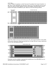
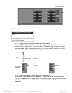
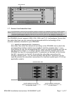
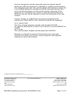
1.5.4 Verify the Connection
Turn your power source(s) on. The PWR (power) LED on both the interface module
and management module faceplates will illuminate solid green to indicate the
modules are receiving power.
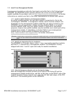
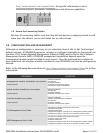
1.6 Establish Your Uplink Connections
For further connection and configuration information, refer to the installation
instructions of your particular UIM or MIM model at
http://www.nettonet.com/support/docs
.
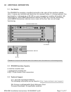
DC POWER
TERMINAL
Negative (-)
Terminal
Ring
Terminal
NEGATIVE
POWER LEAD
CAUTION
Be sure to attach THE POSITIVE LEAD TO THE POSITIVE TERMINAL and the NEGATIVE LEAD TO THE
NEGATIVE TERMINAL as indicated on your IPD4000E terminal block labels.
CAUTION
The power source(s) connected to the IPD4000E must be equipped with a disconnect device such
as an On/Off switch. Otherwise, an appropriately rated circuit breaker must be installed on each
power circuit to be used. In the case of an emergency, hazardous voltages will not be removed
from the IPD4000E until all power sources have been either turned off or disconnected from the
chassis.
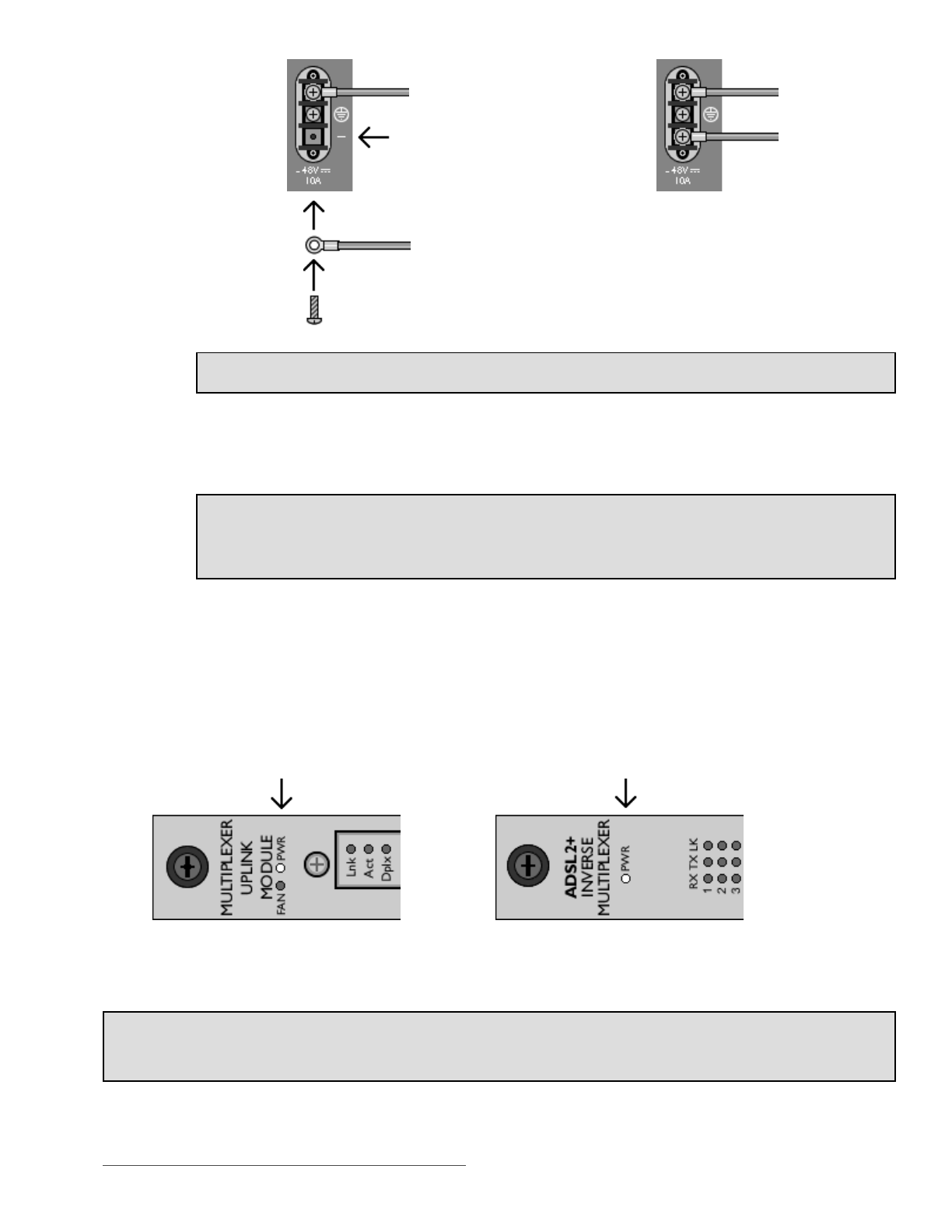
MANAGEMENT
MODULE
Power LED
INTERFACE
MODULE
Power LED
NOTE
No configuration is necessary for Uplink Interface Modules (UIMs) or Media Interface Modules (MIMs), as installed on
the management module(s) in your IPD4000E, to operate at default settings. However, if you wish to run your uplink
connections at settings other than the UIM or MIM defaults, Net to Net recommends configuring the UIM or MIM
prior to connection.
Page 10 of 17IPD4000E Installation Instructions 220-0000097 rev01