


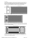
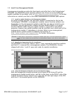
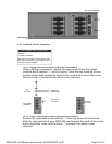

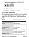
1.4.2 Align the Interface Module with the Slot Module Guides
With the interface module PCB facing UP and the interface module model name,
and Net to Net logo, on the RIGHT side of the module faceplate (facing towards
you), align the left and right edges of the PCB with the slot module guides of the
chosen slot on the IPD4000E.
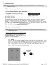
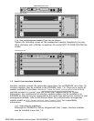
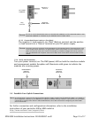
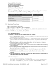
1.4.3 Slide the Interface Module Firmly into the Chassis
Tighten the fastening screws on the interface module faceplate by turning them
clockwise with a Phillips screwdriver. Be careful NOT TO OVER-TIGHTEN the
screws.
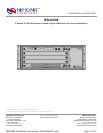
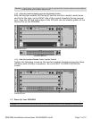
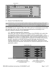
1.5 Power Up Your IPD4000E
CAUTION
If a blank plate is removed from slot 2-4, it must be replaced with an interface module. DO NOT OPERATE
YOUR IPD4000E WITH AN EMPTY MODULE SLOT.
Slot Module Guides
INTERFACE MODULE
Fastening Screws
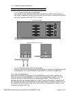
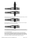
CAUTION
Turn your DC power source(s) OFF until you have completed connection of the IPD4000E as outlined below.
Page 7 of 17IPD4000E Installation Instructions 220-0000097 rev01