


1.0 INSTALLATION
1.1 Unpack and Inspect the Equipment
The following components should be included:
If there is visible damage, do not attempt to connect the device. Contact Customer
Support: customers in Europe, the Middle East and Africa please call 44-0-1635-
570953 or email support-emea@nettonet.com; customers in the United States please
call 1-877-638-2638 or email support@nettonet.com. All other customers please call 1-
603-427-0600 or email support@nettonet.com.
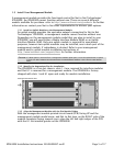
1.2 Select a Site for Installation
1.2.1 Tabletop
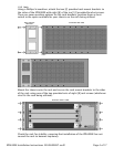
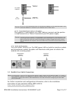
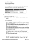
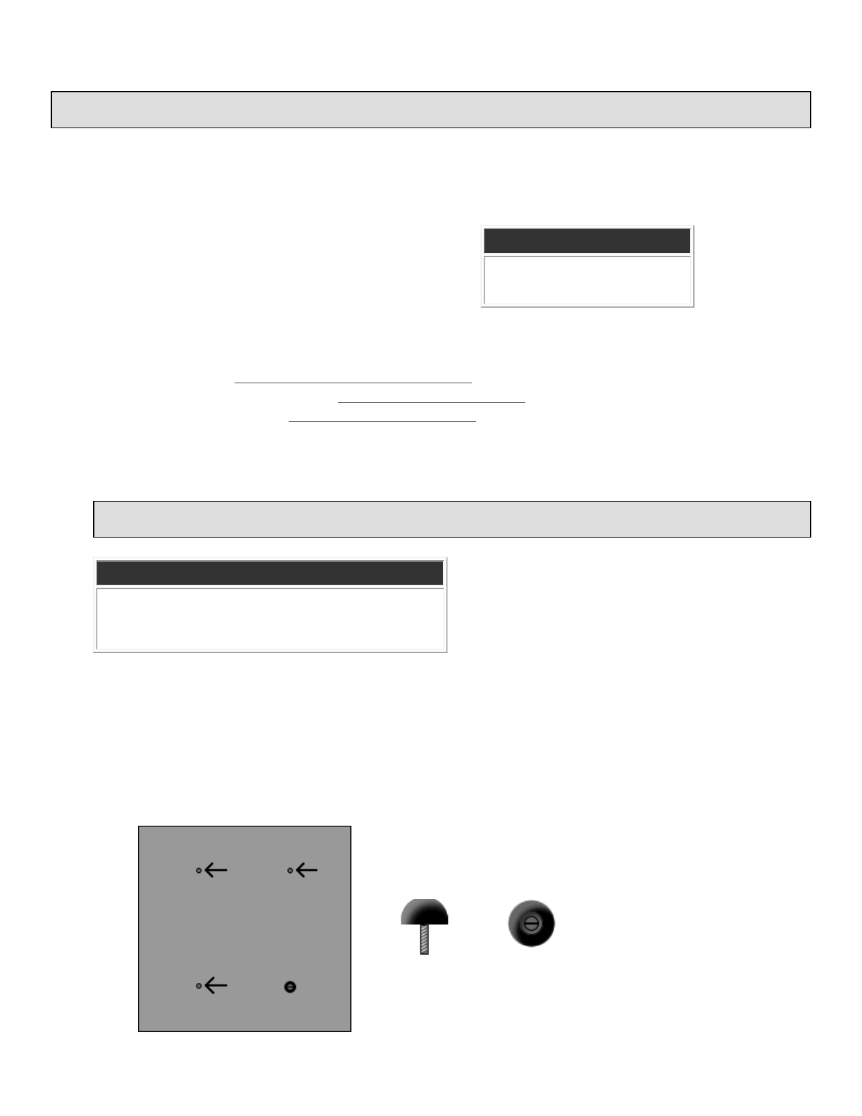
Insert the four [4] provided rubber bumper screws into the mounting holes at the
bottom four corners of the IPD4000E chassis for surface grip. Position and secure
all connecting cables such that they will not become a tripping hazard or pull
loose from the chassis. Ensure that the air supply vents around the top and
bottom edges of the chassis are not blocked.
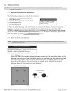
CAUTION
Net to Net Technologies strongly recommends the use of proper electrostatic discharge (ESD) precautions when
handling this equipment.
1 IPD4000E with 1 fan module and 12 blank plates
4 Rubber Bumper Screws
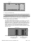
2 Rack Mount Brackets (either 19" or 23", as ordered)
10#6 Phillips Bracket Screws
8 #10 Phillips Rack Screws
8 #12 Phillips Rack Screws
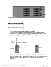
CHASSIS SPECIFICATIONS
7" High x 17" Wide x 18" Deep
(17.8 cm x 43.2 cm x 46 cm)
28 lbs (12.73 kg)
NOTE
The IPD4000E is designed for installation in a Restricted Access area where admittance is limited to trained and
authorized service personel.
OPERATING REQUIREMENTS
Operating Temperature: -40°F to 149°F (-40°C to 65°C)
Non-Operating Temperature: -40°F to 158°F (-40°C to 70°C)
Humidity: 5% to 95%, non-condensing
Altitude: -200ft to 16,500ft (-60m to 5,000m)
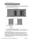
IPD4000E BOTTOM VIEW
RUBBER BUMPER
SCREW
Side
Top
Front Rear
Page 3 of 17IPD4000E Installation Instructions 220-0000097 rev01