


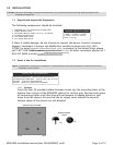

1.5.1 Establish a Ground Connection
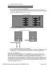
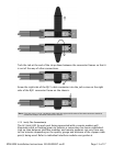
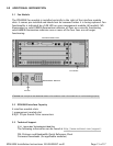
1.5.1.1 Connect a Ground Wire to the IPD4000E
Line up the 2-hole terminal lug of your ground wire with the two holes on
the small, unpainted section on the back of your chassis. Secure the terminal
lug to the chassis with two #10-32 screws.
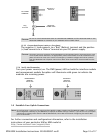
1.5.1.2 Connect the Ground Wire to a Frame Ground
Ground wire connection can vary from location to location, although typically
all equipment in a Central Office is grounded to a common copper bus.
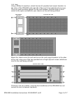
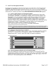
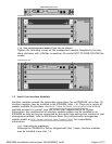
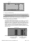
1.5.2 Select a Terminal Block
Either terminal block on the back of the IPD4000E may be used to power the
chassis; only one terminal block is required for operational purposes. The two
terminal blocks on the IPD4000E are independent feeds. Chassis power is
supplied by only one terminal block at a time; the second supply is merely back-
up. Likewise, the two terminal blocks do not load-share. Each terminal block must
be supplied with adequate Amps to run the chassis independently; power is not
cumulative between the two.
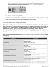
CAUTION
DO NOT operate your IPD40000E without a ground connection.
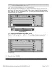
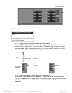
IPD4000E REAR VIEW
Ground Connection for 2-Hole Terminal Lug
GROUND CONNECTION CLOSE-UP
Page 8 of 17IPD4000E Installation Instructions 220-0000097 rev01