


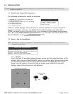
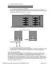

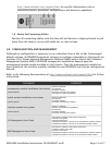
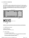
1.7.2 Detach the Velcro Strap
Detach the Velcro Strap from the female RJ21 connector port: lift the Velcro tab
from the bottom and pull the strap upward to open, leaving it looped under the
right side of the connector frame.
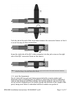
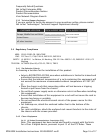
1.7.3 Position the RJ21 Connector
Slide the male RJ21 connector of your interface cable underneath the Velcro, from
the left, and press it firmly into the female RJ21 connector port on the chassis.
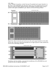
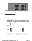
1.7.4 Secure the RJ21 Connector
Pull the Velcro strap upward, making sure that it is snug against the connector,
then pull the strap back down, such that the Velcro layers stick to one another
across the top of the connector.
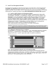
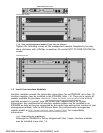
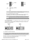
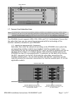
EXCEPTION
For the TIM1500-24 and EIM2000-24 interface modules, the A connectors provide the subcriber
connections for ports 1-12 and the B connectors provide the subscriber connections for ports 13-24.
FEMALE RJ21 CONNECTOR A
FOR INTERFACE MODULE SLOT 3
MALE RJ21 CONNECTOR OF
YOUR INTERFACE CABLE
Page 12 of 17IPD4000E Installation Instructions 220-0000097 rev01