


1.5.3 Establish a Power Connection
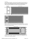
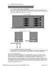
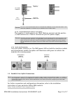
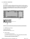
1.5.3.1 Connect Your Positive Power Lead to the Terminal Block
Using a Phillips Screwdriver, remove the upper screw from the chosen
terminal block (labeled "+" on the chassis). Slide the ring terminal of your
positive power lead around the shaft of the screw and re-insert the screw
into the same "+" terminal from which it was removed.
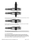
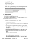
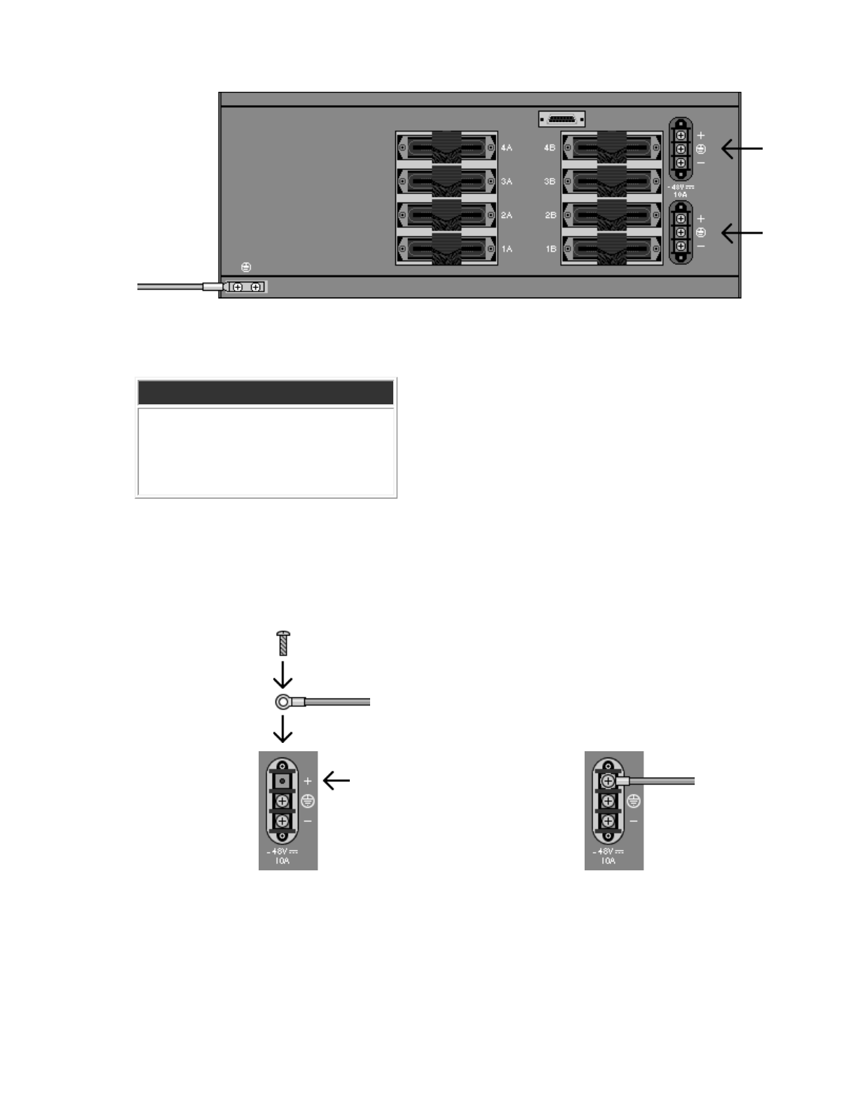
1.5.3.2 Connect Your Negative Power Lead to the Terminal Block
Remove the right-hand screw (labeled "-") from the same terminal block.
Slide the ring terminal of your NEGATIVE lead around the shaft of the screw
and re-insert the screw into the same "-" terminal from which it was
removed.
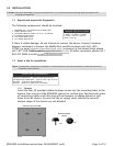
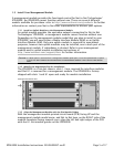
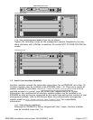
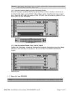
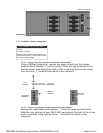
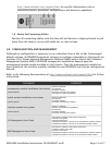
DC Terminal Blocks
DC POWER SPECIFICATIONS
-48V DC
10 Amps maximum
Although actual power draw depends upon
chassis configuration, a fully loaded chassis
averages around 6 Amps.
Ring
Terminal
POSITIVE
POWER LEAD
DC POWER
TERMINAL
Positive (+)
Terminal
Page 9 of 17IPD4000E Installation Instructions 220-0000097 rev01