


Contents
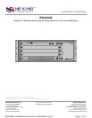
1.0 INSTALLATION
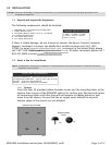
1.1 Unpack and Inspect the Equipment
1.2 Select a Site for Installation
1.2.1 Tabletop
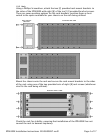
1.2.2 Rack
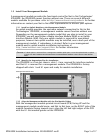
1.3 Install Your Management Module
1.3.1 Install an Uplink Module on the Management Module
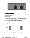
1.3.2 Identify the Appropriate Slot for Installation
1.3.3 Align the Management Module with the Slot Module Guides
1.3.4 Slide the Management Module Firmly into the Chassis
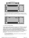
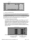
1.4 Install Your Interface Module(s)
1.4.1 Select a Slot for Installation
1.4.2 Align the Interface Module with the Slot Module Guides
1.4.3 Slide the Interface Module Firmly into the Chassis
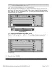
1.5 Power Up Your IPD4000E
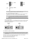
1.5.1 Establish a Ground Connection
1.5.1.1 Connect a Ground Wire to the IPD4000E
1.5.1.2 Connect the Ground Wire to a Frame Ground
1.5.2 Select a Terminal Block
1.5.3 Establish a Power Connection
1.5.3.1 Connect Your Positive Power Lead to the Terminal Block
1.5.3.2 Connect Your Negative Power Lead to the Terminal Block
1.5.3.3 Connect Both Power Leads to a Fuse Panel
1.5.4 Verify the Connection
1.6 Establish Your Uplink Connections
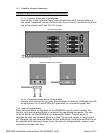
1.7 Connect Your Subscriber Lines
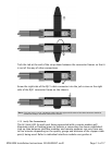
1.7.1 Identify the Appropriate RJ21 Connector(s)
1.7.2 Detach the Velcro Strap
1.7.3 Position the RJ21 Connector
1.7.4 Secure the RJ21 Connector
1.7.5 Verify The Connection(s)
1.8 Secure the Connecting Cables
2.0 CONFIGURATION AND MANAGEMENT
3.0 ADDITIONAL INFORMATION
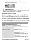
3.1 Fan Module
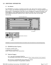
3.2 IPD4000E Interface Capacity
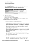
3.3 Technical Support
3.3.1 Net to Net Technologies' Web Site
3.3.2 Technical Support Engineers
3.4 Regulatory Compliance
3.4.1 Site Selection Criteria
3.4.2 Class A Equipment
3.4.2.1 US Federal Communications Commission (FCC)
3.4.2.2 Industry Canada
3.4.2.3 Europe
Page 2 of 17IPD4000E Installation Instructions 220-0000097 rev01