


1.7 Connect Your Subscriber Lines
The IPD4000E chassis supports ADSL, IDSL, SDSL and T1/E1 technologies. Ensure that
the subscriber lines you are connecting correspond with the technology of the
interface module(s) installed in your IPD4000E.
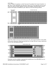
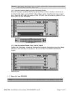
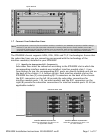
1.7.1 Identify the Appropriate RJ21 Connector(s)
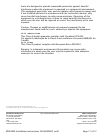
Subscriber lines must be connected according to the IPD4000E slot in which the
corresponding interface module was installed. Interface module slots 1-4 run
from bottom to top; the corresponding RJ21 ports are directly behind each slot on
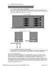
the back of the chassis (1-4, bottom to top). Each interface module slot on the
IPD4000E has two [2] corresponding RJ21 connectors on the back of the chassis:
the RJ21 connectors on the left (A) provide the subscriber connections for
interface module ports 1-24 (on most models) and the RJ21 connectors on the
right (B) provide the subscriber connections for interface module ports 25-48 (on
applicable models).
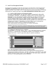
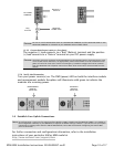
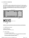
Uplink Module
NOTE
No configuration is necessary for the interface module(s) installed in your IPD4000E to operate at default settings.
However, if you wish to run your subscriber connections at settings other than the factory defaults, Net to Net
recommends configuring the interface module(s) prior to connection. Refer to the installation instructions for your
particular interface module model(s) at http://www.nettonet.com/support/docs
for configuration information.
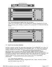
IPD4000E REAR VIEW
Interface Module B connectors
subscriber connections for ports 25-48
(on applicable models)
Interface Module A Connectors
subscriber connections for ports 1-24
(on most models)
Page 11 of 17IPD4000E Installation Instructions 220-0000097 rev01