


19
Clocking: Network
(default)
Options: Network, Internal, External
Network: This is the most commonly used setting when connect
ing to a carrier’s network. In this mode, the unit recovers the
clock from the received signal and uses it to transmit data. In
this way the unit remains synchronized to a master clock. In
campus applications, one of the units must be set to Internal
clock, and the other end is set to Network clock. At all times,
there must be only one clock source. Otherwise, clock slips
and framing errors and bit errors may occur.
Internal: This is commonly used in campus applications, where
the unit is not connected to the public telephone network
directly. In this mode, the unit uses the on-board oscillator as
the transmit clock source.
External: This is a special mode that should only be used with
the Unframed format. In this mode, the unit requires a 1.544
Mhz clock signal from the DTE via the external clock pin on
the DTE interface connector. Most applications will use
Network or Internal clock modes.
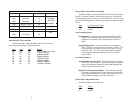
Line Build Out (dB): 0 – 133 feet, 0 dB
(default)
Options: 0 – 133 feet, 0 dB
133 – 266 feet
266 – 399 feet
399 – 533 feet
533 - 655 feet
-7.5 dB
-15.0 dB
-22.5 dB
This controls the transmitter signal strength and pulse shape. For
most applications, the default setting will suffice. When connecting to a
carrier connection, the carrier will determine what LBO is necessary. 0
dB provides the highest signal strength and therefore the longest dis-
tance, while –15.0 dB provides the lowest usable signal strength. The
last setting, –22.5 dB, is usually only used to test the line and should
not be used in normal applications.
d
e
20
ESF Data Link: ANSI T1.403
Options: ANSI T1.403, AT&T TR54016
ANSI T1.403: This ANSI developed standard (see ANSI T1.403-
1995: Network-to-Customer Installation—DS1 Metallic
Interface) uses the FDL to send and receive one second
Performance Report Messages (PRMs). The messages con-
tain the NI performance over the last four seconds. Thus, up
to three consecutive messages may be lost without loss of
information. It is available only with ESF. When ANSI T1.403
is selected, requests to send AT&T performance reports (ref.
AT&T TR 54016) are ignored.
AT&T TR54016: Developed by AT&T, this FDL method differs
principally from the ANSI method in two ways: First, the ANSI
method transmits messages continuously, whereas the AT&T
method transmits a performance report only upon a request
from the remote end for a report. Second, the AT&T method
provides a historical summary, up to the last 24 hours, of NI
performance. Only the service provider or special test equip-
ment can send these requests. When AT&T TR54016 is
selected, ANSI PRMs are still transmitted by the unit, but only
PRMs sent by the carrier will be recognized. To receive PRMs
from another customer unit (i.e., in a campus application),
select ANSI T1.403. When the frame is not ESF, the FDL is
disabled.
ESF Carrier Loops: Enabled
(default)
Options: Enabled, Disabled
The ESF format provides the CO the ability to put the customer
installation’s NetLink-T1™ into loopback mode. The NetLink-T1™ rec-
ognizes these special messages that are sent over the FDL. When
enabled, the unit will respond to these loopback commands and go into
or out of loopback mode. When disabled, the unit will not respond,
although it still recognizes the loopback commands. When in loopback,
the unit will remain in loopback until a loopback exit command is
received or when the loopback timer times out. See Unit Options
(Section 3.2.4) to make Loop Timeout choices. This feature allows the
remote user to regain control should one be locked out after a loop-
back is initiated.
f
g