


32
4.3 POWER CONNECTION
The NetLink-T1™ offers three ways to supply external power: AC
power, DC power and interface power.
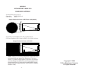
4.3.1 Using the AC Power Supply (120VAC or 100-240VAC)
The NetLink-T1™ uses a 5VDC, 300mA 120VAC or universal input
100-240VAC, power supply. The universal input power supply is
equipped with a male IEC-320 power entry connector. This power sup-
ply connects to the NetLink-T1™ by means of a barrel jack on the rear
panel. There are a variety of international power cords available for
the universal power supply. The NetLink-T1™ powers up as soon as it
is plugged into an AC outlet–there is no power switch.
4.3.2 Supplying DC Power
You may bypass the DC wall adapter and supply DC power directly
to the NetLink T1™ power supply jack. DC power supplied must be
5VDC ±5%, 300mA minimum, center positive, and can be supplied via
a barrel type plug with 2.1/5.5/10mm I.D./O.D./Shaft Length dimen-
sions.
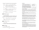
4.3.3 Supplying Power via pin KK
You may also supply DC power directly to pin KK of the V.35 inter-
face. DC Power supplied to pin KK must be 5VDC ± 5%, 300mA mini-
mum.
NOTE: NetLink-T1™ is factory configured to accept power from
the enclosed DC wall adapter (See Sections 4.3.1 and 4.3.2
above). If you wish to supply power via pin KK on the interface,
you must change the setting of the
power supply jumper
on the
printed circuit board See Appendix E. All power sources must
be SELV (Circuit, Safety Extra Low Voltage) specified. (See CEN-
ELEC EN60950, Section 1.2.8.5)
31
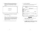
4.0 INSTALLATION
The NetLink-T1™ is equipped with DTE, network, and power
interfaces. This section briefly describes connection to each.
4.1 DTE INTERFACE CONNECTION
The DTE interface is a V.35 DCE presented as an M/34 male con-
nector. This interface is designed to plug directly into a DTE interface
(See Appendix D for V.35 interface pin assignments).
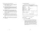
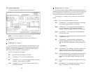
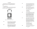
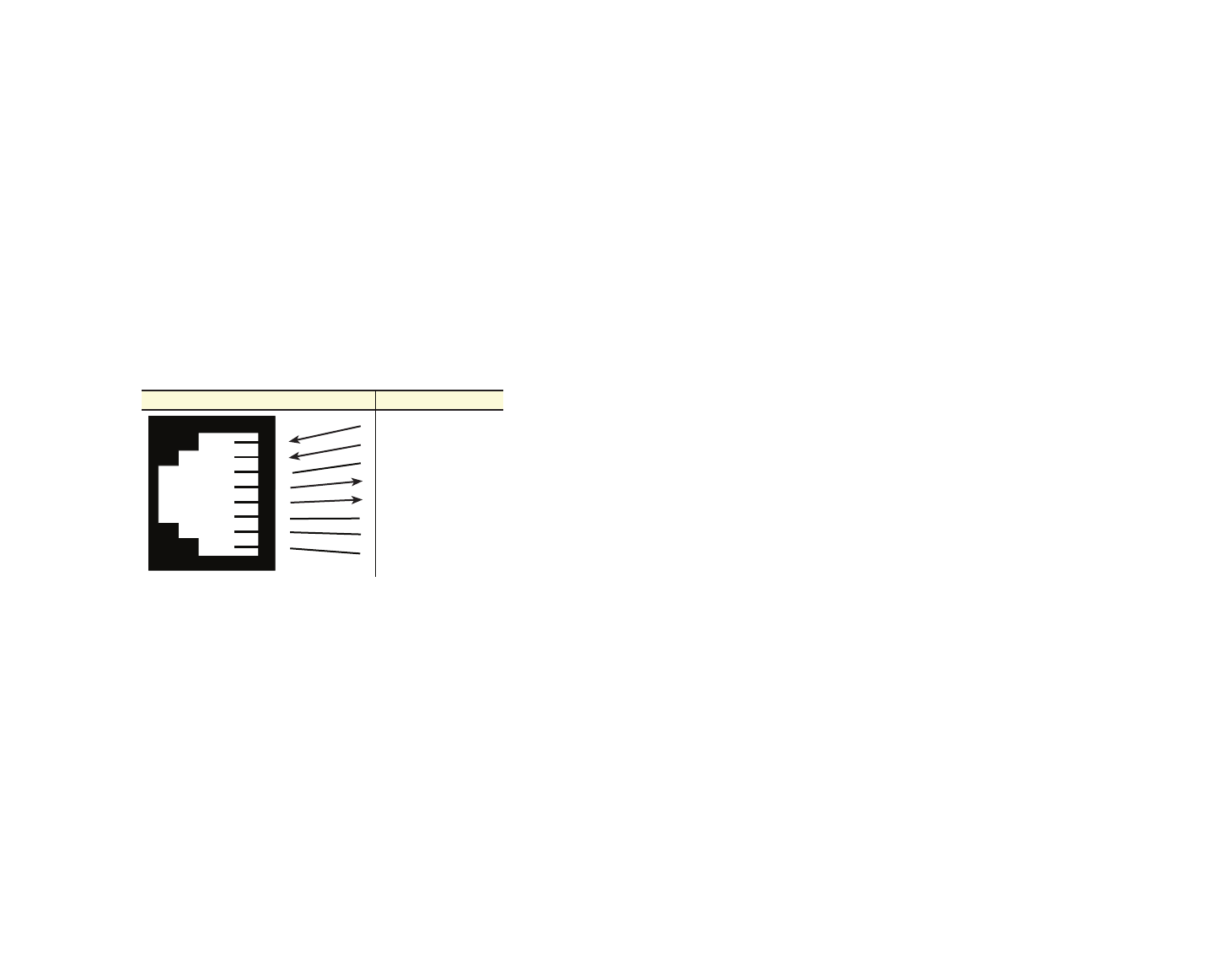
4.2 NETWORK INTERFACE CONNECTION
The Network Line Interface is an eight position keyed modular jack
configured as a RJ-48C. This interface will need to be configured to
match the line parameters (i.e. framing, line coding, etc.) supplied by
the central office.
NOTE: If the NetLink-T1™ is being used for private short range
modem applications, the twisted pair cable connected to its port
will need to be a cross-over cable. See Appendix D for Interface
pin assignments.
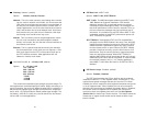
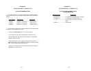
Figure 3. NetLink-T1™ twisted pair line interface.
1
2
3
4
5
6
7
8
1
2
3
4
5
6
7
8
(RX) Receive (Ring)
(RX) Receive (Tip)
Shield
(TX) Transmit (Ring)
(TX) Transmit (Tip)
Shield
No connection
No connection
Signal NameRJ-48C Jack