


7
2.3 SUPPORTED APPLICATIONS
The NetLink-T1™ CSU/DSU provides a T1 (DS1) network termi-
nation between the service provider and customer premises equipment
(CPE) such as a router. The Netlink-T1™ can also be used as a high-
speed short haul modem for campus applications.
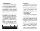
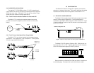
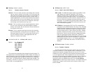
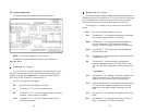
2.3.1 The 2710 as the Interface between the Telco and CPE
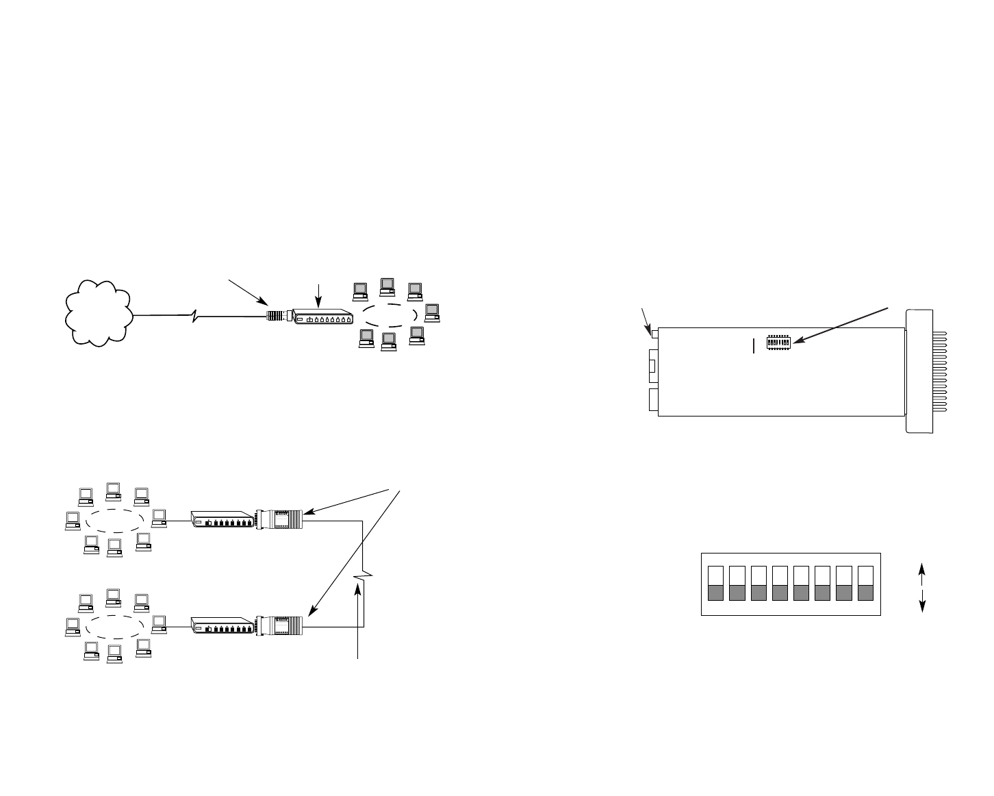
The NetLink-T1™ provides the interface between the service
provider and customer equipment, such as a router or switch (See
below).
2.3.2 The 2710 as a High-Speed Short Range Modem
The NetLink-T1™ can also be installed into high-speed campus
applications. In this application, a pair of NetLink-T1™ units operate
as short range modems (See below).
RXD
LOS
ALM
ERR
T/L
PWR
TXD
Model 2700
RXD
LOS
ALM
ERR
T/L
PWR
TXD
Model 2700
Model 2710
NetLink-T1™
Model 2710s
Router
1.544Mbps
or nx56/64
1.544MBps
or nx56/64
LAN
T1
Network
Up to 6000 Feet
(1.83 km)
8
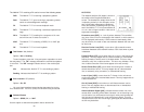
3.0 CONFIGURATION
The Model 2710 features configuration capability via hardware
switches or a software control port. This section describes all possible
hardware and software switch configurations of the NetLink-T1™.
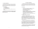
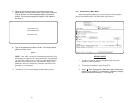
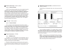
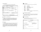
3.1 DIP SWITCH CONFIGURATION
The Model 2710 has eight internal DIP switches that allow configu-
ration for a wide range of applications. The eight switches are
accessed by opening the plastic case with a small screwdriver. Figure
1 (below) shows the location of the DIP switches on the bottom of the
printed circuit board.
The Model 2710 DIP switches (Switches SW1 - SW8) can be con-
figured as either “On” or “Off”. Figure 2 (below) shows the orientation
of the DIP switches with respect to ON/OFF positions.
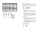
Default positions for Switches SW1-SW8 are shown in the table on
the following page. Descriptions of each switch follow the table.
Figure 1. Model 2710 Series bottom view, showing location of DIP switches
ON
12345678
DIP Switches
12345678
ON
OFF
ON
Figure 2. Close up of DIP switches showing ON/OFF positions.
ON
OFF
Software Configuration Port