


Users Manual Model 656/636 Maintenance / Adjustments • 35
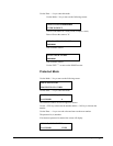
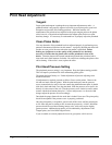
R48 R50 R51 R49 R47 R54R52
11 12 13 18 16 8 10
14 17
3
21
22
9
4
J9 J1
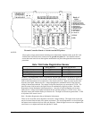
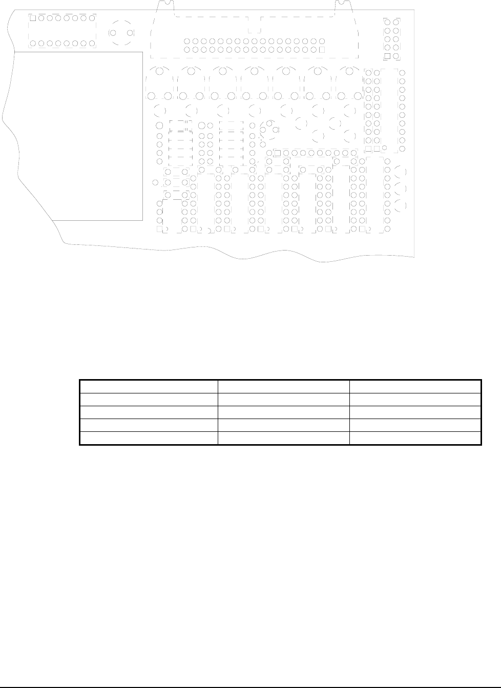
DIP Switch
Thermal Controller Board as viewed from back of
p
rinter
12345678
10. +5VDC ok
9. 24V enable
8. RESERVED
7. Headlift Sensor
6. Full Stack Sensor
5. RESERVED
4. Opt. Reflective Sensor
3. Registration Sensor
2. Bottom Ink Sensor
1. Top Ink Sensor
Bank of
Lights
+5VDC
GND
NOTICE:
All test point voltage measurements including sensor adjustments should be made on the DC scale
with the black lead of the meter connected to the ground test point 22. Care should be taken to
ensure that meter leads do not short against unintentional test points throughout the measurement
procedures.
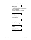
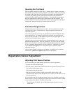
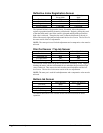
Hole / Slot Index Registration Sensor
Sensor Blocked Sensor Not Blocked
Test Point:
TP13 TP13
Adjustment Pot
R51 R51
#3 Light Status:
On Off
Desired Voltage:
> 3.50 VDC < 0.75 VDC
The Hole / Slot Registration Sensor in conjunction with the light bar allows the printer to register to
preprinted media. The low level is the more crucial of the two adjustments. Note that the same pot is
used for both adjustments and a compromise value must be achieved. Begin by removing the stock
from the sensor path. Measure the low voltage throughout the mechanical travel of the sensor by
sliding it inboard and outboard. The voltage at all points should not vary more than 0.75VDC. If it
does the sensor slide bar and or the light bar must be mechanically aligned (see Hole / Slot Index
Registration Sensor Mechanical Adjustment below). Once this is achieved find the web location
where the low voltage is the highest and adjust the pot until the reading is 0.75VDC or less. Now
block the sensor path with the media you intend to run. The high level should be greater than 3.5VDC
at all points of the sensor’s travel.
Hole / Slot Index Registration Sensor Mechanical Adjustment:
There are two areas that can be adjusted to correct the voltage readings. The upper sensor square bar
may be loosened from the back of the printer and rotated. The second adjustment is to loosen the light
bar mount screws and move the bar in the web direction. When the light bar screws are retightened be
careful not to over tighten and brake the light bar PC board.