


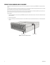
16 C3683M (3/09)
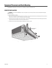
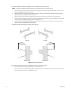
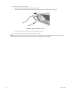
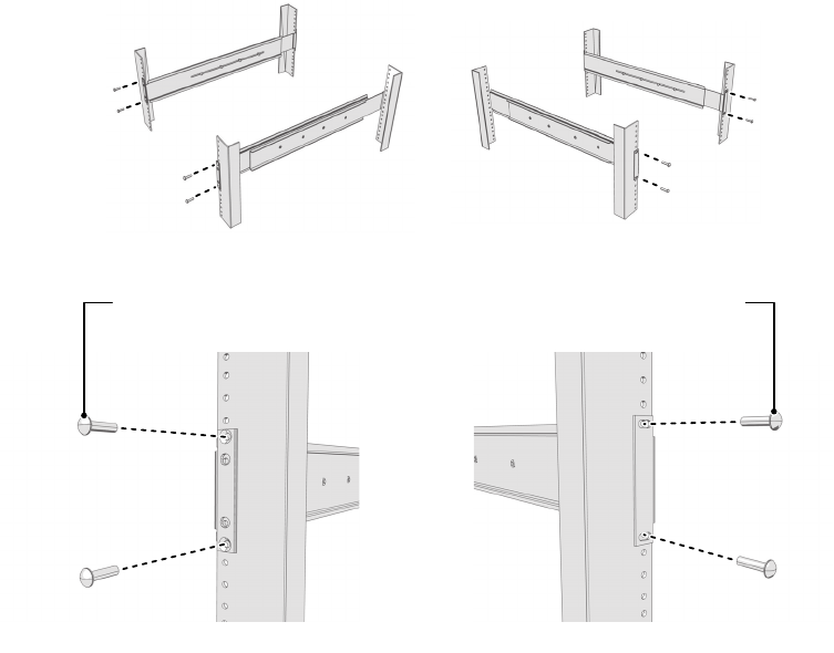
6. Attach one support rail assembly to the equipment rack in the desired location (refer to Figure 9):
NOTE: Th
e support rail assemblies are identical and may be used on either the right or left side of the rack.
a. Position the ear of the front-mount rail against the front of the equipment rack. Align the top and bottom holes in the ear of th
e rail
with the threaded holes (or cage nuts) in the rack.
b. Using two 10-32 x 0.5-inch Phi
llips flat head screws, attach the ear of the rail to the front of the rack. Insert the screws from the
outside of the rack, pointing toward the back of the rack.
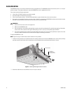
c. Adjust the rails to the correct depth of the equipment rack by slid
ing the rear-mount rail to the back of the equipment rack.
d. Position the ear of the rear-mount rail against the rear exterio
r of the equipment rack. Align the top and bottom holes in the ear of the
rail section with the threaded holes (or cage nuts) in the equipment rack.
e. Using two 10-32 x 0.75-inch Phillips pan head screws, attach the ear of the rail to the rear of the rack. Insert the screws from the
outside of the rack, pointing toward the front of the rack.
Figure 9. Attaching Support Rails
7. Repeat step 6 for the second support rail assembly (refer to Figure 9).
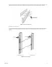
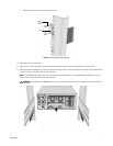
8. Attach one rack rail spacer to the front of the equipment rack (refer to Figure 10 on page 17):
a. Position the bottom hole of the spacer above the ear of the front-mount rail.
b. Insert two 10-32 x 0.5-inch
Phillips flat head screws into the spacer, one in the top hole and one in the bottom hole. Leave the middle
hole empty; the top thumbscrew on the NSM5200 will use it.
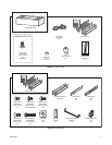
(4) SCREWS
10-32 X 0.75-INCH
PHILLIPS PAN HEAD
(4) SCREWS
10-32 X 0.5-INCH
PHILLIPS FLAT HEAD
REAR-MOUNT RAILFRONT-MOUNT RAIL
RACK FRONT RACK REAR