


C3683M (3/09) 21
Connections
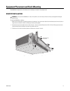
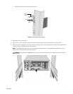
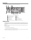
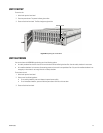
Figure 16. Rear Panel Layout
Familiarize yourself with the
NSM5200 rear panel before connecting any equipment to the unit.
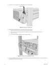
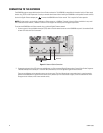
CONNECTING POWER
The NSM5200 is equipped with two hot-swappable power supplies. These autoranging power supplies adapt automatically to voltages from
100 to 240 VAC (50/60 Hz). You should also install an uninterruptible power supply (UPS), which is not supplied. UPS devices maintain a limited
amount of backup battery power if the main power fails. Refer to Appendix B: Installing an Uninterruptible Power Supply (UPS) on page 30 for
more information.
NOTE: Connect each power supply to a different branch circuit. This ensures optimal performance, reduces possible video loss, and reduce
s
power leakage to a safe level.
To connect the power supplies:
1. Connect each power cord to a power supply connector.
2. Connect the other end of each power cord to the appropriate power source.
When connected, the power supply status indicators glow solid red. As soon as the unit starts, the indicators glow solid green. During operation,
if either indicator is not lit or glows red, there is a problem with a power supply.
ì Power Supply Connectors (hot-swappable) t Ethernet Port 1
î Power Supplies (hot-swappable) u VGA Port
ï Power Supply LEDs (status) ~í Serial Port
ñ Mute button ~â USB 2.0 Ports (2)
ó Fibre Channel Connector ~ä Connector for Keyboard (purple)
r Mini-SAS Connector ~ã Connector for Mouse (green)
s Ethernet Port 2 (reserved for future use) ~å Power Supply (reserved for future use)